Check first when you have a trouble
664
PROTECTIVE FUNCTIONS
6.6 Check first when you have a trouble
For Real sensorless vector control and vector control, also refer to the troubleshooting on page 198 (speed control), page 226
(torque control), and page 252 (position control).
NOTE
• If the cause is still unknown after every check, it is recommended to initialize the parameters, set the required parameter
values and check again.
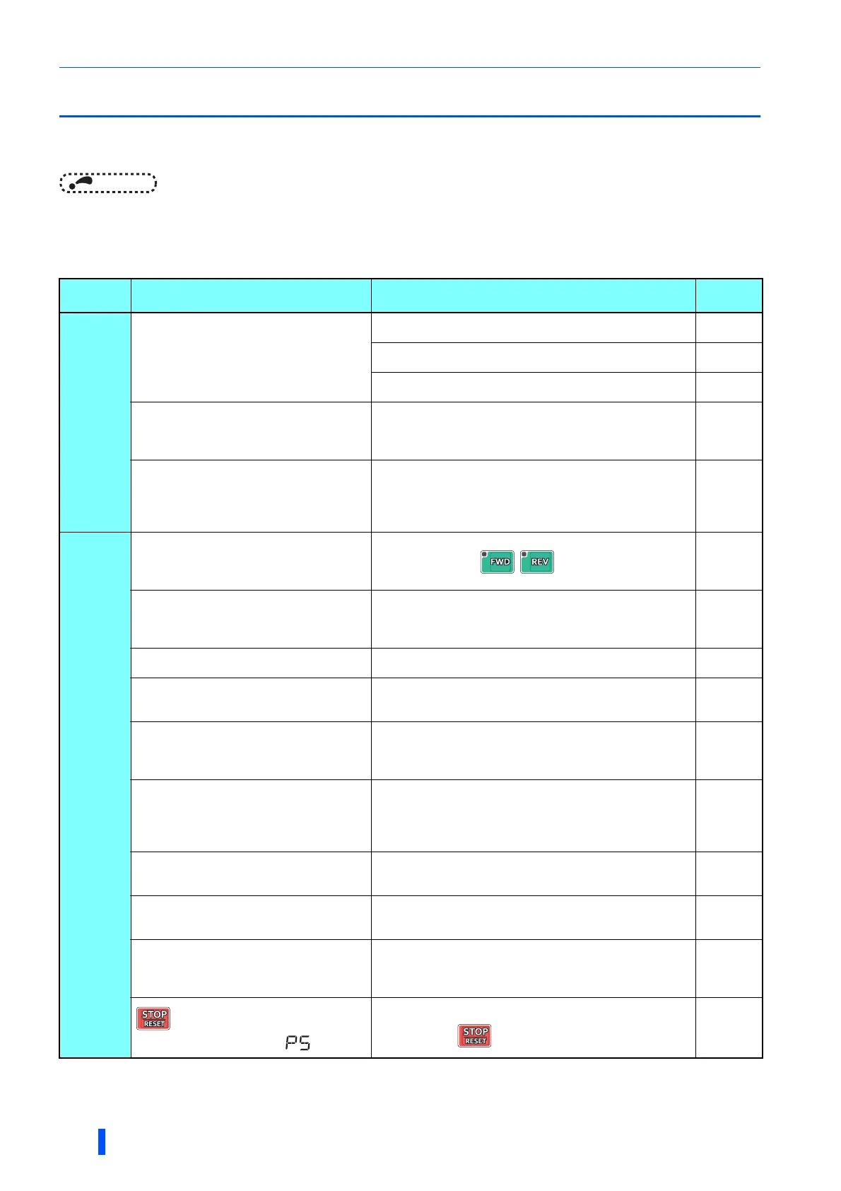
6.6.1 Motor does not start
Check
points
Possible cause Countermeasure
Refer to
page
Main
Circuit
Appropriate power supply voltage is not
applied.
(Operation panel display is not provided.)
Power on a molded case circuit breaker (MCCB), an earth
leakage circuit breaker (ELB), or a magnetic contactor (MC).
Check for the decreased input voltage, input phase loss, and
wiring.
If only the control power is ON when using a separate power
source for the control circuit, turn ON the main circuit power.
54
Motor is not connected properly.
Check the wiring between the inverter and the motor.
If the electronic bypass function is active, check the wiring of
the magnetic contactor (MC) between the inverter and the
motor.
38
The jumper across P/+ to P1 is disconnected.
A DC reactor (FR-HEL) is not connected.
Securely fit a jumper across P/+ and P1.
When using a DC reactor (FR-HEL), remove the jumper across
P/+ to P1, and then connect the DC reactor.
Connect the DC reactor securely when required according to
the capacity.
38, 79
Input
signal
Start signal is not input.
Check the start command source, and input a start signal.
PU operation mode: /
External operation mode: STF/STR signal
309
Both the forward and reverse rotation start
signals (STF, STR) are input simultaneously.
Turn ON only one of the forward and reverse rotation start
signals (STF or STR).
When the STF and STR signals are turned ON simultaneously
in the initial setting, a stop command is given.
45
Frequency command is zero. (FWD or REV
LED on the operation panel is flickering.)
Check the frequency command source and enter a frequency
command.
309
AU signal is not ON when terminal 4 is used
for frequency setting. (FWD or REV LED on
the operation panel is flickering.)
Turn ON the AU signal.
Turning ON the AU signal activates terminal 4 input.
406
Output stop signal (MRS) or reset signal
(RES) is ON. (FWD or REV LED on the
operation panel is flickering.)
Turn MRS or RES signal OFF.
Inverter starts the operation with a given start command and a
frequency command after turning OFF MRS or RES signal.
Before turning OFF, ensure the safety.
45
CS signal is OFF while the automatic restart
after instantaneous power failure function is
selected (Pr.57 Restart coasting time
9999). (FWD or REV LED on the operation
panel is flickering.)
Turn ON the automatic restart after instantaneous power
failure/flying start (CS) signal.
When the CS signal is assigned to an input terminal, automatic
restart operation is enabled when the CS signal is turned ON.
528
Jumper connector of sink - source is
incorrectly selected. (FWD or REV LED on the
operation panel is flickering.)
Check that the control logic switchover jumper connector is
correctly installed.
If it is not installed correctly, input signal is not recognized.
49
Wiring of encoder is incorrect.
(Under encoder feedback control or vector
control)
Check the wiring of encoder. 65
Voltage/current input switch is not correctly set
for analog input signal (0 to 5 V/0 to 10 V, 4 to
20 mA). (FWD or REV LED on the operation
panel is flickering.)
Set Pr.73 Analog input selection, Pr.267 Terminal 4 input
selection, and a voltage/current input switch correctly, then
input an analog signal in accordance with the setting.
406
was pressed.
(Operation panel indication is (PS).)
During the External operation mode, check the
method of
restarting from a input stop from PU
.
260, 649

 Loading...


