(T) Multi-Function Input Terminal Parameters
PARAMETERS
411
5
GROUP
T
5.12.3 Analog input compensation
Addition compensation (Pr.242, Pr.243)
Auxiliary input characteristics
Addition compensation or fixed ratio analog compensation (override) with terminal 2 set to auxiliary input is applicable
to the multi-speed operation or terminal 2/terminal 4 speed setting signal (main speed).
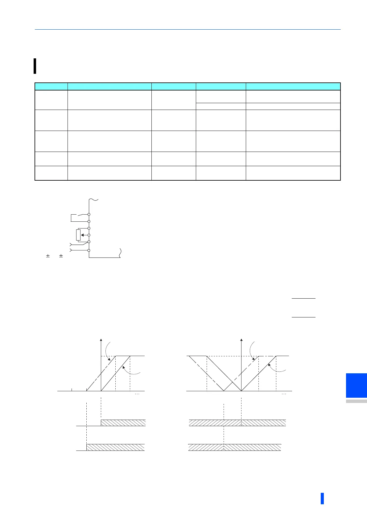
Pr. Name Initial value Setting range Description
73
T000
Analog input selection
1
0 to 3, 6, 7, 10 to 13,
16, 17
Addition compensation
4, 5, 14, 15 Override compensation
242
T021
Terminal 1 added
compensation amount
(terminal 2)
100% 0 to 100%
Set the percentage of addition
compensation when terminal 2 is set to
the main speed.
243
T041
Terminal 1 added
compensation amount
(terminal 4)
75% 0 to 100%
Set the percentage of addition
compensation when terminal 4 is set to
the main speed.
252
T050
Override bias
50% 0 to 200%
Set the percentage of override function
bias side compensation.
253
T051
Override gain
150% 0 to 200%
Set the percentage of override function
gain side compensation.
Example of addition
compensation connection
• A compensation signal is addable to the main speed setting for such as synchronous
or continuous speed control operation.
• Setting a value of "0 to 3, 6, 7, 10 to 13, 16, and 17" to Pr.73 adds the voltage
between terminals 1 and 5 to the voltage signal of the terminals 2 and 5.
• When Pr.73= "0 to 3, 6, or 7", and if the result of addition is negative, it is regarded as
0 and the operation is stopped. When Pr.73 = "10 to 13, 16, or 17", the operation is
reversed (polarity reversible operation) with STF signal ON.
• The terminal 1 compensation input is addable to the multi-speed setting or terminal 4
(initial value: 4 to 20 mA).
• The degree of addition compensation to terminal 2 is adjustable with Pr.242.
The degree of addition compensation to terminal 4 is adjustable with Pr.243.
= terminal 2 input + terminal 1 input
= terminal 4 input + terminal 1 input
10
2
5
Forward
rotation
Inverter
STF
SD
1
Auxiliary input
0 to 10V( 5V)
Analog command value
with use of terminal 2
Analog command value
with use of terminal 4
Output frequency
When voltage across
terminals 2 and 5 is 2.5V
(5V)
When voltage
across terminals
2 and 5 is 0V
+5V
(+10V)
Terminal 1
0
-2.5V
(-5V)
-5V
(-10V)
STF Signal
ON
Forward rotation
Forward rotation
(a) When Pr.73 setting is 0 to 5
Output frequency
When voltage across
terminals 2 and 5 is 2.5V
(5V)
When voltage
across terminals
2 and 5 is 0V
+5V
(+10V)
Terminal 1
0
-2.5V
(-5V)
-5V
(-10V)
STF Signal
ON
Forward rotation
Forward rotation
(b) When Pr.73 setting is 10 to 15
Reverse rotation
Reverse rotation
+2.5V
(+5V)
+2.5V
(+5V)
STF Signal
ON
STF Signal
ON

 Loading...


