(N) Operation via communication and its settings
PARAMETERS
557
5
GROUP
N
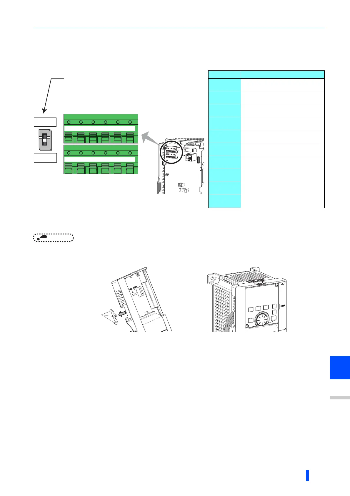
5.15.2 Wiring and configuration of RS-485 terminals
RS-485 terminal layout
Connection of RS-485 terminals and wires
• The size of RS-485 terminal block is the same as the control circuit terminal block.Refer to page 51 for the wiring method.
NOTE
• To avoid malfunction, keep the RS-485 terminal wires away from the control circuit board.
• When the FR-A820-01250(22K) or lower, or the FR-A840-00620(22K) or lower is used with a plug-in option, lead the wires
through the hole on the side face of the front cover for wiring of the RS-485 terminals.
• When the FR-A820-01540(30K) of higher, or the FR-A840-00770(30K) or higher is used with a plug-in option, lead the wires
on the left side of the plug-in option for wiring of the RS-485 terminals.
Name Description
RDA1
(RXD1+)
Inverter receive +
RDB1
(RXD1-)
Inverter receive -
RDA2
(RXD2+)
Inverter receive +
(for branch)
RDB2
(RXD2-)
Inverter receive -
(for branch)
SDA1
(TXD1+)
Inverter send +
SDB1
(TXD1-)
Inverter send -
SDA2
(TXD2+)
Inverter send +
(for branch)
SDB2
(TXD2-)
Inverter send -
(for branch)
P5S
(VCC)
5V
Permissible load current 100 mA
SG
(GND)
Earthing (grounding)
(connected to terminal SD)
Terminating resistor switch
Initially-set to "OPEN".
Set only the terminating resistor switch of
the remotest inverter to the "100Ω" position.
OPEN
100Ω
+-+
TXD RXD
-
VCC GND
+-+
TXD RXD
-
VCC GND
RDA1
(RXD1+)
RDB1
(RXD1-)
RDA2
(RXD2+)
RDB2
(RXD2-)
SDA1
(TXD1+)
SDB1
(TXD1-)
SDA2
(TXD2+)
SDB2
(TXD2-)
P5S
(VCC)
SG
(GND)
P5S
(VCC)
SG
(GND)
Cut off with
a nipper, etc.

 Loading...


