(M) Monitor display and monitor output signal
PARAMETERS
375
5
GROUP
M
5.11.4 Monitor display selection for terminals FM/CA
and AM
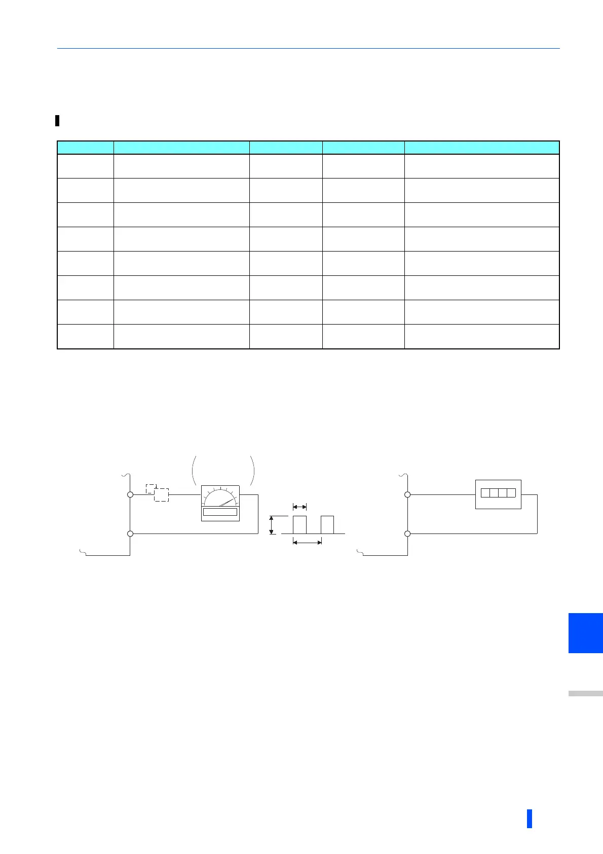
Terminal FM calibration (C0 (Pr.900))
• The terminal FM is preset to output pulses. By setting C0 (Pr.900), the meter connected to the inverter can be calibrated by
parameter setting without use of a calibration resistor.
• Using the pulse train output of the terminal FM, a digital display can be provided to connect a digital counter.The monitor
value is 1440 pulses/s output at the full-scale value of the monitor description list (on page 360) (Pr.54 FM/CA terminal
function selection).
Not needed when the operation panel or the parameter unit is used for calibration.
Use a calibration resistor when the indicator (frequency meter) needs to be calibrated by a neighboring device because the indicator is located
far from the inverter.
However, the frequency meter needle may not deflect to full-scale if the calibration resistor is connected.In this case, perform calibration using
the operation panel or parameter unit.
In the initial setting, 1 mA full-scale and 1440 pulses/s terminal FM are used at 60 Hz.
• Calibrate the terminal FM in the following procedure.
1) Connect an indicator (frequency meter) across terminals FM and SD of the inverter. (Note the polarity. The terminal FM
is positive.)
2) When a calibration resistor has already been connected, adjust the resistance to "0" or remove the resistor.
3) Refer to the monitored item list (page 360) and set Pr.54.
When the running frequency or inverter output current is selected on the monitor, set the running frequency or current
value at which the output signal will be 1440 pulses/s, using Pr.55 Frequency monitoring reference or Pr.56 Current
monitoring reference beforehand. Normally, at 1440 pulses/s the meter deflects to full-scale.
4) If the meter needle does not point to maximum even at maximum output., calibrate it with C0(Pr.900).
By using the operation panel or parameter unit, terminals FM, CA and AM can be adjusted (calibrated) to the full scale.
Pr. Name Initial value Setting range Description
C0 (900)
M310
FM/CA terminal calibration
Calibrates the scale of the meter
connected to terminals FM and CA.
C1 (901)
M320
AM terminal calibration
Calibrates the scale of the analog meter
connected to terminal AM.
C8 (930)
M330
Current output bypass signal
0% 0 to 100%
Set the signal value at the minimum
analog current output.
C9 (930)
M331
Current output bypass
current
0% 0 to 100%
Set the current value at the minimum
analog current output.
C10 (931)
M332
Current output gain signal
100% 0 to 100%
Sets the signal value when the analog
current output is at maximum.
C11 (931)
M333
Current output gain current
100% 0 to 100%
Set the current value at the maximum
analog current output.
867
M321
AM output filter
0.01 s 0 to 5 s Set the terminal AM output filter.
869
M334
Current output filter
0.01 s 0 to 5 s Set the terminal AM output filter.
The parameter number in parentheses ( ) is the one for use with the LCD operation panel and the parameter unit.
8VDC
T2
T1
Pulse width T1: Adjust using calibration parameter C0
Pulse cycle T2: Set with Pr.55 (frequency monitor)
Set with Pr.56 (current monitor)
(Digital indicator)
(-)
1440 pulses/s(+)
FM
SD
Indicator
1mA full-scale
analog meter
(+)
1mA
FM
SD
Calibration
resistor ∗1
(-)

 Loading...


