(M) Monitor display and monitor output signal
PARAMETERS
373
5
GROUP
M
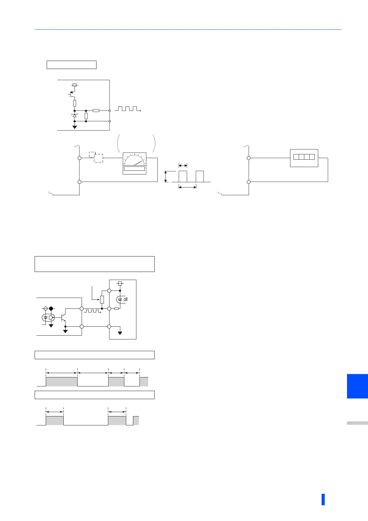
Terminal FM pulse train output (Pr.291)
• Two kinds of pulse trains can be output to the terminal FM.
Not needed when the operation panel or the parameter unit is used for calibration.
Use a calibration resistor when the indicator (frequency meter) needs to be calibrated by a neighboring device because the indicator is located
far from the inverter.
However, the frequency meter needle may not deflect to full-scale if the calibration resistor is connected. In this case, calibrate additionally with
the operation panel or parameter unit.
In the initial setting, 1 mA full-scale and 1440 pulses/s terminal FM are used at 60 Hz.
FM output circuit
• When Pr.291
Pulse train I/O selection = "0 (initial value) or 1", this is FM
output with a maximum output of 8 VDC and 2400 pulses/s.
The pulse width can be adjusted by using the operation panel or parameter
unit and calibration parameter C0(Pr.900) FM/CA terminal calibration.
• Commands can be sent (such as inverter output frequency) by connecting
a 1 mA full-scale DC ammeter or a digital meter.
High-speed pulse train output circuit
(example of connection to pulse counter)
• When Pr.291 Pulse train I/O selection = "10, 11, 20, 21, 100", this
is high-speed pulse train output for open collector output. A
maximum pulse train of 55k pulses/s is outputted.
There are two types of pulse width: "50% duty" and "fixed ON
width"; this cannot be adjusted with the calibration parameter C0
(Pr.900) FM/CA terminal calibration.
The pulses may weaken due to stray capacitance in the wiring if the
wiring is long, and the pulse counter will be unable to recognize the
pulses. Connect the open collector output to the power source with a
pull-up resistor if the wiring is too long.
Check the pulse counter specs for the pull-up resistance. The resistance
should be at 80 mA of the load current or less.
Pulse of Pr.291 = "10, 11"
• When Pr.291 = "10
, 11", the pulse cycle is 50% duty (ON width and
OFF width are the same).
• When Pr.291 = "20
, 21, 100", the pulse ON width is output at a fixed
width (approx. 10 s).
• At the "100" setting, the same pulse train from the pulse train input
(terminal JOG) will be outputted. This is used when running at a
synchronized speed with more than one inverter. (Refer to page
324.)
"HIGH" indicates when the open collector output transistor is OFF.
Pulse of Pr.291 = "20, 21, 100"
Inverter
24V
2.2K
20K
3.3K
SD
FM
8VDC
T2
T1
Pulse width T1: Adjust using calibration parameter C0
Pulse cycle T2: Set with Pr.55 (frequency monitor)
Set with Pr.56 (current monitor)
(Digital indicator)
(-)
1440 pulses/s(+)
FM
SD
Indicator
1mA full-scale
analog meter
(+)
1mA
FM
SD
Calibration
resistor ∗1
(-)
FM
SD
Inverter
Pull up resistance
∗3
Pulse counter
Hi
∗4
Low
50%duty
50%duty
Hi
∗4
Low
Approx. 10
μs
Approx. 10
μs

 Loading...


