(A) Application parameters
522
PARAMETERS
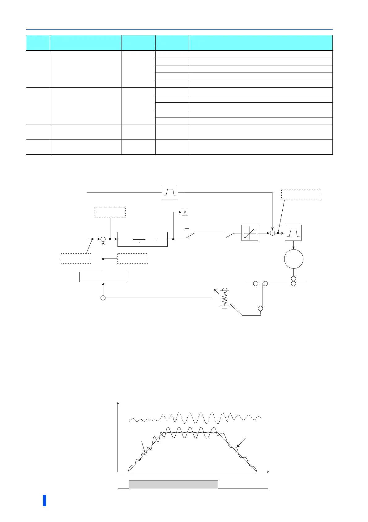
Block diagram of dancer control
The main speed can be selected in all operation modes, External (analog voltage input, multi-speed), PU (digital frequency setting) and
Communication (RS-485).
Outline of dancer control
• Dancer control is performed by setting "40 to 43" in Pr.128 PID action selection. The main speed command is the speed
command for each operation mode (External, PU and communication). PID control is performed by the dancer roll position
detection signal, and the control result is added to the main speed command. For the main speed acceleration/deceleration
time, set the acceleration time to Pr.44 Second acceleration/deceleration time and the deceleration time to Pr.45
Second deceleration time.
609
A624
PID set point/deviation
input selection
2
1 Input set point from terminal 1
2 Input set point from terminal 2
3 Input set point from terminal 4
4 Input set point via CC-Link communication
5 Input set point by PLC function
610
A625
PID measured value
input selection
3
1 Input measured value from terminal 1
2 Input measured value from terminal 2
3 Input measured value from terminal 4
4 Input measured value via CC-Link communication
5 Input measured value by PLC function
1134
A605
PID upper limit
manipulated value
100% 0 to 100% Set the upper limit of PID action.
1135
A606
PID lower limit
manipulated value
100% 0 to 100% Set the lower limit of PID action.
Pr. Name
Initial
value
Setting
range
Description
Limit
Ratio
Acceleration/deceleration
of main speed
Main speed command
∗1
Dancer roll
setting point
Pr.133
Terminal 4
Potentiometer
Dancer roll position detection
PID control
PID deviation
PID feedback
PID set point
Target frequency
X14
Pr.128 = 40, 41
Pr.128 = 42, 43
Acceleration/
deceleration
+
-
Kp(1+ +Td S)
Ti S
1
Convert to 0 to 100%
IM
+
+
STF
PID adding value
Main speed
ON
Output frequency
Time
Output frequency

 Loading...


