Inverter rating
690
SPECIFICATIONS
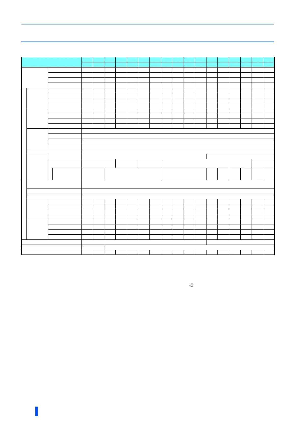
8.1 Inverter rating
200 V class
The applicable motor capacity indicated is the maximum capacity applicable for use of the Mitsubishi 4-pole standard motor.
The 0.2 kW motor capacity is applicable under V/F control only.
The rated output capacity indicated assumes that the output voltage is 220 V for 200 V class.
The % value of the overload current rating indicated is the ratio of the overload current to the inverter's rated output current. For repeated duty, allow time for the inverter
and motor to return to or below the temperatures under 100% load.
The maximum output voltage does not exceed the power supply voltage. The maximum output voltage can be changed within the setting range. However, the maximum
point of the voltage waveform at the inverter output side is the power supply voltage multiplied by about .
Value for the built-in brake resistor
Value for the ND rating
The rated input current indicates a value at a rated output voltage. The impedance at the power supply side (including those of the input reactor and cables) affects the
rated input current.
The power supply capacity is the value when at the rated output current. It varies by the impedance at the power supply side (including those of the input reactor and
cables).
FR-DU08: IP40 (except for the PU connector section)
Model FR-A820-[ ]
00046 00077 00105 00167 00250 00340 00490 00630 00770 00930 01250 01540 01870 02330 03160 03800 04750
0.4K 0.75K 1.5K 2.2K 3.7K 5.5K 7.5K 11K 15K 18.5K 22K 30K 37K 45K 55K 75K 90K
Applicable motor
capacity (kW)
SLD 0.75 1.5 2.2 3.7 5.5 7.5 11 15 18.5 22 30 37 45 55 75 90/110 132
LD 0.75 1.5 2.2 3.7 5.5 7.5 11 15 18.5 22 30 37 45 55 75 90 110
ND (initial setting) 0.4 0.75 1.5 2.2 3.7 5.5 7.5 11 15 18.5 22 30 37 45 55 75 90
HD 0.2 0.4 0.75 1.5 2.2 3.7 5.5 7.5 11 15 18.5 22 30 37 45 55 75
Output
Rated capacity
(kVA)
SLD 1.82.94 6.410131924293548597189120145181
LD 1.62.73.75.88.8121722273243536581110132165
ND (initial setting) 1.1 1.9 3 4.2 6.7 9.1 13 18 23 29 34 44 55 67 82 110 132
HD 0.61.11.93 4.26.79.1131823293444556782110
Rated current
(A)
SLD 4.67.710.516.7253449637793125154187233316380475
LD 4.2 7 9.6 15.2 23 31 45 58 70.5 85 114 140 170 212 288 346 432
ND (initial setting) 3 5 8 11 17.5 24 33 46 61 76 90 115 145 175 215 288 346
HD 1.5 3 5 8 11 17.5 24 33 46 61 76 90 115 145 175 215 288
Overload
current rating
SLD 110% 60 s, 120% 3 s (inverse-time characteristics) at surrounding air temperature 40°C
LD 120% 60 s, 150% 3 s (inverse-time characteristics) at surrounding air temperature 50°C
ND (initial setting) 150% 60 s, 200% 3 s (inverse-time characteristics) at surrounding air temperature 50°C
HD 200% 60 s, 250% 3 s (inverse-time characteristics) at surrounding air temperature 50°C
Rated voltage
Three-phase 200 to 240 V
Regenerative
braking
Brake transistor Built-in FR-BU2 (Option)
Maximum brake
torque
150% torque/3%ED
100% torque/
3%ED
100% torque/
2%ED
20% torque/continuous
10% torque/
continuous
FR-ABR
(when the option is
used)
150% torque/
10%ED
100% torque/10%ED 100% torque/6%ED
Power supply
Rated input
AC voltage/frequency
Three-phase 200 to 240 V 50 Hz/60 Hz
Permissible AC voltage fluctuation 170 to 264 V 50 Hz/60 Hz
Permissible frequency fluctuation ±5%
Rated input
current (A)
SLD 5.3 8.9 13.2 19.7 31.3 45.1 62.8 80.6 96.7 115 151 185 221 269 316 380 475
LD 5 8.3 12.2 18.3 28.5 41.6 58.2 74.8 90.9 106 139 178 207 255 288 346 432
ND (initial setting) 3.9 6.3 10.6 14.1 22.6 33.4 44.2 60.9 80 96.3 113 150 181 216 266 288 346
HD 2.3 3.9 6.3 10.6 14.1 22.6 33.4 44.2 60.9 80 96.3 113 150 181 216 215 288
Power supply
capacity (kVA)
SLD 2 3.45 7.5121724313744587084103120145181
LD 1.9 3.2 4.7 7 11 16 22 29 35 41 53 68 79 97 110 132 165
ND (initial setting) 1.52.44 5.48.6131723303743576982101110132
HD 0.9 1.5 2.4 4 5.4 8.6 13 17 23 30 37 43 57 69 82 82 110
Protective structure (IEC 60529)
Enclose type (IP20) Open type (IP00)
Cooling system Self-cooling Forced air cooling
Approx. mass (kg) 2.0 2.2 3.3 3.3 3.3 6.7 6.7 8.3 15 15 15 22 42 42 54 74 74

 Loading...


