Control circuit
INSTALLATION AND WIRING
51
2
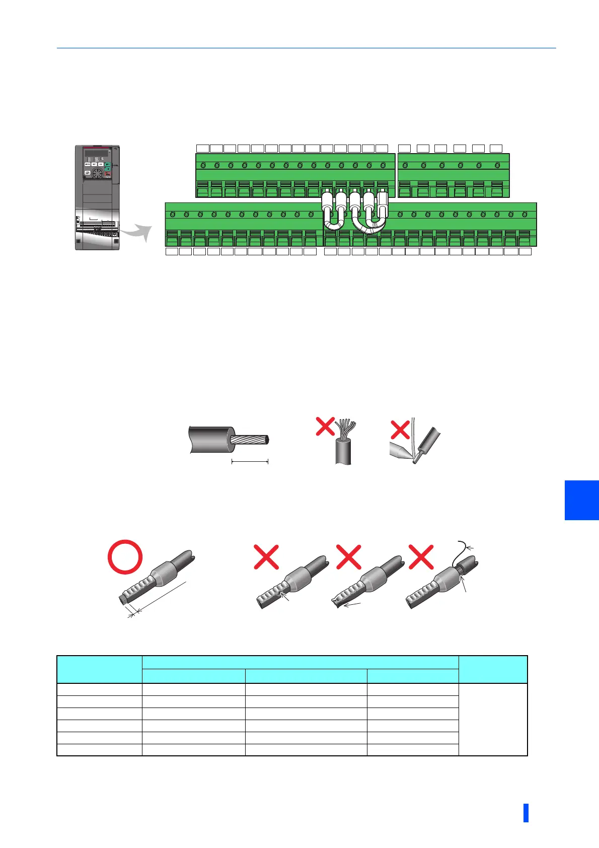
2.6.3 Wiring of control circuit
Control circuit terminal layout
• Recommended cable gauge: 0.3 to 0.75 mm
2
This terminal operates as the terminal FM for the FM type, and as the terminal CA for the CA type.
Wiring method
• Power supply connection
For the control circuit wiring, strip off the sheath of a cable, and use it with a blade terminal. For a single wire, strip off the
sheath of the wire and apply directly.
Insert the blade terminal or the single wire into a socket of the terminal.
(1)Strip off the sheath for the below length. If the length of the sheath peeled is too long, a short circuit may occur with
neighboring wires. If the length is too short, wires might come off.
Wire the stripped cable after twisting it to prevent it from becoming loose. In addition, do not solder it.
(2)Crimp the blade terminal.
Insert wires to a blade terminal, and check that the wires come out for about 0 to 0.5 mm from a sleeve.
Check the condition of the blade terminal after crimping. Do not use a blade terminal of which the crimping is inappropriate,
or the face is damaged.
• Blade terminals commercially available (as of February 2012)
Phoenix Contact Co., Ltd.
Cable stripping size
Cable gauge
(mm
2
)
Ferrule terminal model
Crimping tool
name
With insulation sleeve Without insulation sleeve For UL wire
0.3 AI 0,5-10WH — —
CRIMPFOX 6
0.5 AI 0,5-10WH — AI 0,5-10WH-GB
0.75 AI 0,75-10GY A 0,75-10 AI 0,75-10GY-GB
1 AI 1-10RD A 1-10 AI 1-10RD/1000GB
1.25, 1.5 AI 1,5-10BK A 1,5-10 AI 1,5-10BK/1000GB
0.75 (for two wires) AI-TWIN 2 0,75-10GY — —
A ferrule terminal with an insulation sleeve compatible with the MTW wire which has a thick wire insulation.
Applicable for the terminal A1, B1, C1, A2, B2, C2.
AM
2 5 4 1 F/C
+24
SD SD S1 S2 PC A1 B1 C1 A2 B2 C2SICSo
SOC
5 10E 10 SE SE SU
RUN
IPF OL FU PC RL RM RH RT AU SD SD CSSTP
MRS RES
STF STR
JOG
∗1
10 mm
Crumpled tip
Wires are not inserted
into the sleeve
Unstranded
wires
Damaged
Wire
Sleeve
0 to 0.5mm (0.02 inch)

 Loading...


