Peripheral devices
18
INSTALLATION AND WIRING
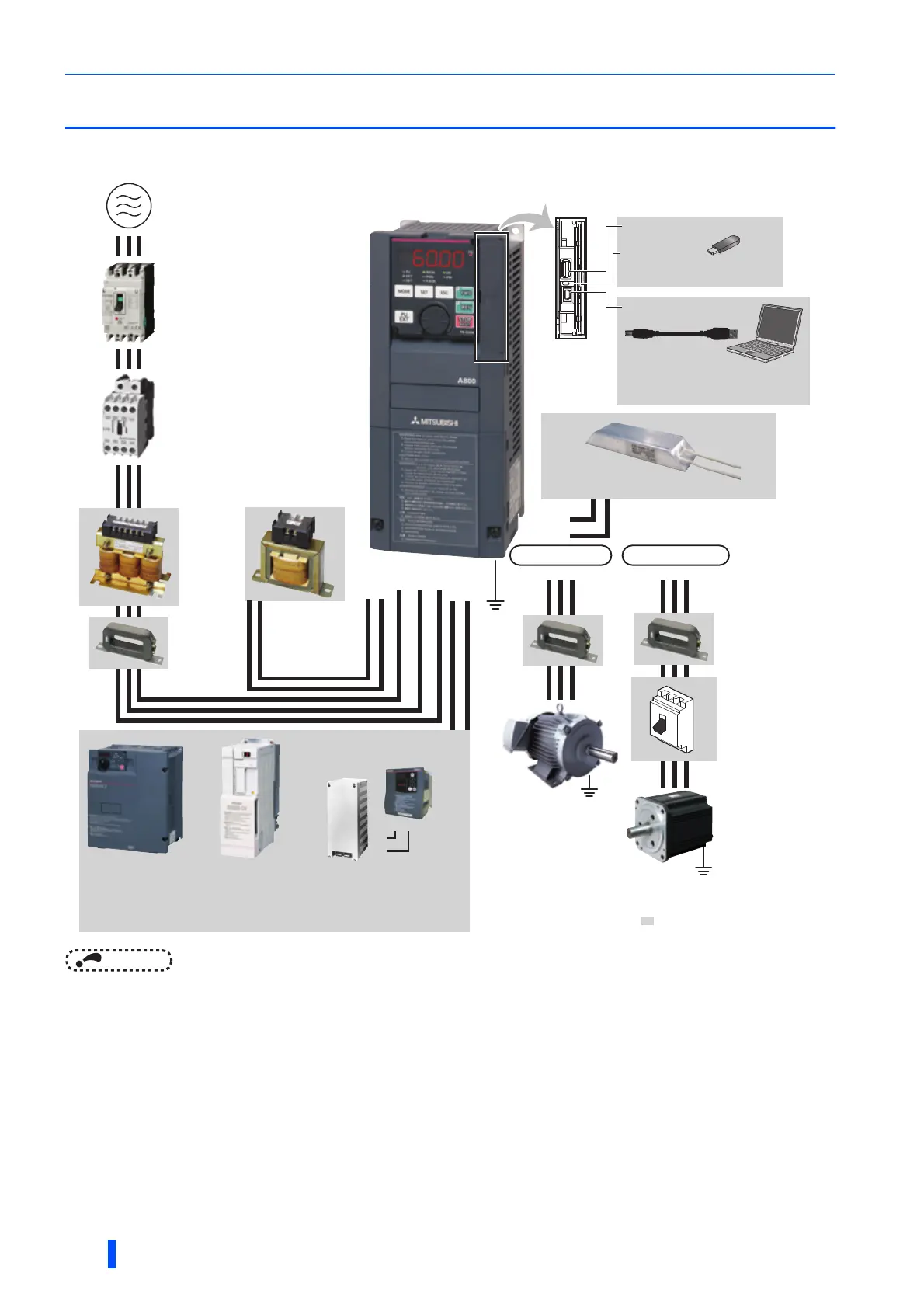
2.1 Peripheral devices
2.1.1 Inverter and peripheral devices
NOTE
• To prevent an electric shock, always earth (ground) the motor and inverter.
• Do not install a power factor correction capacitor or surge suppressor or capacitor type filter on the inverter's output side.
Doing so will cause the inverter to trip or the capacitor and surge suppressor to be damaged. If any of the above devices is
connected, immediately remove it. When installing a molded case circuit breaker on the output side of the inverter, contact
the manufacturer of the molded case circuit breaker.
• Electromagnetic wave interference
The input/output (main circuit) of the inverter includes high frequency components, which may interfere with the
communication devices (such as AM radios) used near the inverter. In this case, activating the EMC filter may minimize
interference. (Refer to page 86.)
• For details of options and peripheral devices, refer to the respective Instruction Manual.
• A PM motor cannot be driven by the commercial power supply.
• A PM motor is a motor with permanent magnets embedded inside. High voltage is generated at the motor terminals while the
motor is running. Before closing the contactor at the output side, make sure that the inverter power is ON and the motor is
stopped.
Earth
(Ground)
R/L1 S/L2 T/L3
P1P/+
N/-P/+
P/+(P3)
PR
P/+
P/+
PR
PR
: Install these options as required.
U
Earth (Ground)
VW
IM connection
PM connection
(c) Moulded case circuit breaker
(MCCB) or earth leakage current
breaker (ELB), fuse
(e) AC reactor
(FR-HAL)
(f) DC reactor
(FR-HEL)
(n) High-duty brake resistor (FR-ABR)
(o) EMC filter
(ferrite core)
(FR-BSF01, FR-BLF)
UVW
Earth (Ground)
(p) Induction motor
(q) Contactor
Example) No-fuse
switch
(DSN type)
(r) IPM motor (MM-CF)
(g) Line noise
filter
(FR-BLF)
(h) High power factor
converter
(FR-HC2)
(i) Power regeneration
common converter
(FR-CV)
(j) Power regeneration
converter (MT-RC)
(l) Resistor unit
(FR-BR, MT-BR5)
(k) Brake unit
(FR-BU2, FR-BU)
(d) Magnetic contactor (MC)
(a) Inverter
(b) Three-phase AC power supply
(m) USB connector
Personal computer
(FR Configurator 2)
USB
USB host
(A connector)
USB device
(Mini B connector)
Communication
status indicator
(LED)(USB host)

 Loading...


