APPENDIX
711
Appendix 3 Parameters (functions) and
instruction codes under different
control methods
Instruction codes are used to read and write parameters in accordance with the Mitsubishi inverter protocol of RS-485 communication.
(For RS-485 communication, refer to page 563.)
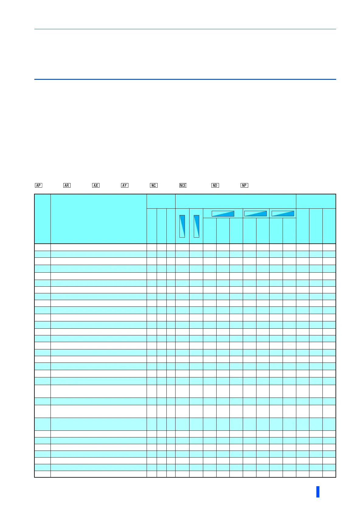
Function availability under each control method is shown as below:
: Available
: Not available
: Available only during position control set by parameter
For "parameter copy", "parameter clear", and "all parameter clear", "" indicates the function is available, and "" indicates the function is not
available.
These parameters are not cleared by the parameter clear (all parameter clear) command, which are sent through RS-485 communication. (For
RS-485 communication, refer to page 563.)
When a communication option is installed, parameter clear (lock release) during password lock (Pr.297 "9999") can be performed only from
the communication option.
Available when the IPM motor MM-CF series is used and the low-speed range high-torque characteristic is enabled (Pr.788 = "9999 (initial
value)").
Reading and writing via the PU connector are available.
Symbols in the table indicate parameters that operate when the options are connected.
FR-A8AP, FR-A8AR, FR-A8AX, FR-A8AY, FR-A8NC, FR-A8NCE, FR-A8ND, FR-A8NP
Pr. Name
Instruction
code
Control method Parameter
Read
Write
Extended
Copy
Clear
All clear
Speed
control
Torque
control
Position
control
Speed
control
Torque
control
Speed
control
Position
control
0 Torque boost 00 80 0
1 Maximum frequency 01 81 0
2 Minimum frequency 02 82 0
3 Base frequency 03 83 0
4 Multi-speed setting (high speed) 04 84 0
5 Multi-speed setting (middle speed) 05 85 0
6 Multi-speed setting (low speed) 06 86 0
7 Acceleration time 07 87 0
8 Deceleration time 08 88 0
9 Electronic thermal O/L relay 09 89 0
10 DC injection brake operation frequency 0A 8A 0
11 DC injection brake operation time 0B 8B 0
12 DC injection brake operation voltage 0C 8C 0
13 Starting frequency 0D 8D 0
14 Load pattern selection 0E 8E 0
15 Jog frequency 0F 8F 0
16 Jog acceleration/deceleration time 10 90 0
17 MRS input selection 11 91 0
18 High speed maximum frequency 12 92 0
19 Base frequency voltage 13 93 0
20
Acceleration/deceleration reference
frequency
14 94 0
21 Acceleration/deceleration time increments 15 95 0
22
Stall prevention operation level
(Torque limit level)
16 96 0
23
Stall prevention operation level
compensation factor at double speed
17 97 0
24 Multi-speed setting (speed 4) 18 98 0
25 Multi-speed setting (speed 5) 19 99 0
26 Multi-speed setting (speed 6) 1A 9A 0
27 Multi-speed setting (speed 7) 1B 9B 0
28 Multi-speed input compensation selection 1C 9C 0
29 Acceleration/deceleration pattern selection 1D 9D 0
30 Regenerative function selection 1E 9E 0
Magnetic fluxMagnetic fluxMagnetic flux
SensorlessSensorlessSensorless

 Loading...


