(D) Operation command and frequency command
PARAMETERS
321
5
GROUP
D
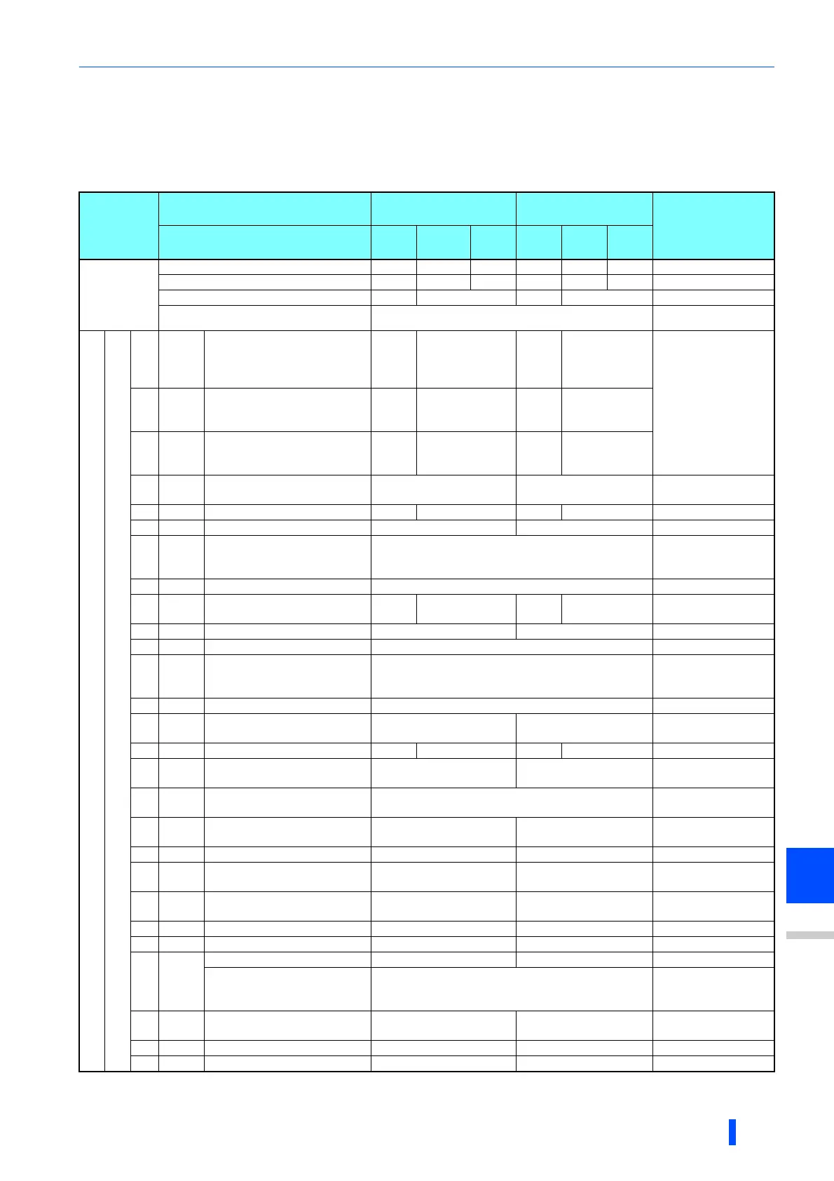
Selection of control source in Network operation mode (Pr.338, Pr.339)
• There are two control sources: the start command source, which controls the signals related to the inverter stand command
and function selection, and the speed command source, which controls signals related to frequency setting.
• The table below shows the commands from the external terminals and communication (RS-485 terminals or
communication option) in the Network operation mode.
Operation
location
selection
Pr.338 Communication operation
command source
0: NET 1: EXT
REMARKS
Pr.339 Communication speed
command source
0:
NET
1: EXT
2:
EXT
0:
NET
1:
EXT
2:
EXT
Fixed
function
(terminal-
equivalent
function)
Running frequency from communication NET NET NET NET
Terminal 2 External
Terminal 4 External External
Terminal 1 Compensation
Selectable function
Pr.178 to Pr.189 setting
0RL
Low-speed operation
command/remote setting
Clear/Stop-on-contact selection
0
NET External NET External
Pr.59 ="0" (multi-
speed)
Pr.59 "0" (remote)
Pr.270 ="1, 3, 11, or
13" (stop-on-contact)
1RM
Middle-speed operation
command/remote setting
deceleration
NET External NET External
2RH
High-speed operation
command/remote
setting acceleration
NET External NET External
3RT
Second function selection
/stop-
on-contact selection 1
NET External
Pr.270 ="1, 3, 11, or
13" (stop-on-contact)
4 AU Terminal 4 input selection Combined Combined
5 JOG Jog operation selection External
6CS
Selection of automatic restart
after instantaneous power
failure, flying start
External
7 OH External thermal relay input External
8 REX 15-speed selection NET External NET External
Pr.59 ="0" (multi-
speed)
9 X9 Third function selection NET External
10 X10 Inverter run enable signal External
11 X11
FR-HC2/FR-CC2 connection,
instantaneous power failure
detection
External
12 X12 PU operation external interlock External
13 X13
External DC injection brake
operation start
NET External
14 X14 PID control valid terminal NET External NET External
15 BRI
Brake opening completion
signal
NET External
16 X16
PU/External operation
switchover
External
17 X17
Load pattern selection forward/
reverse rotation boost
NET External
18 X18 V/F switchover NET External
19 X19
Load torque high-speed
frequency
NET External
20 X20
S-pattern acceleration/
deceleration C switchover
NET External
22 X22 Orientation command NET External
23 LX Pre-excitation/servo ON NET External
24 MRS
Output stop Combined External Pr.79 "7"
PU operation interlock External
Pr.79 = "7"
When X12 signal is
not assigned.
25
STP
(STOP)
Start self-holding selection - External
26 MC Control mode switchover NET External
27 TL Torque limit selection NET External

 Loading...


