(A) Application parameters
554
PARAMETERS
Monitoring the trace status
• The trace status can be monitored on the operation panel by setting "38" in Pr.52 Operation panel main monitor
selection, Pr.774 to Pr.776 (Operation panel monitor selection), or Pr.992 Operation panel setting dial push monitor
selection.
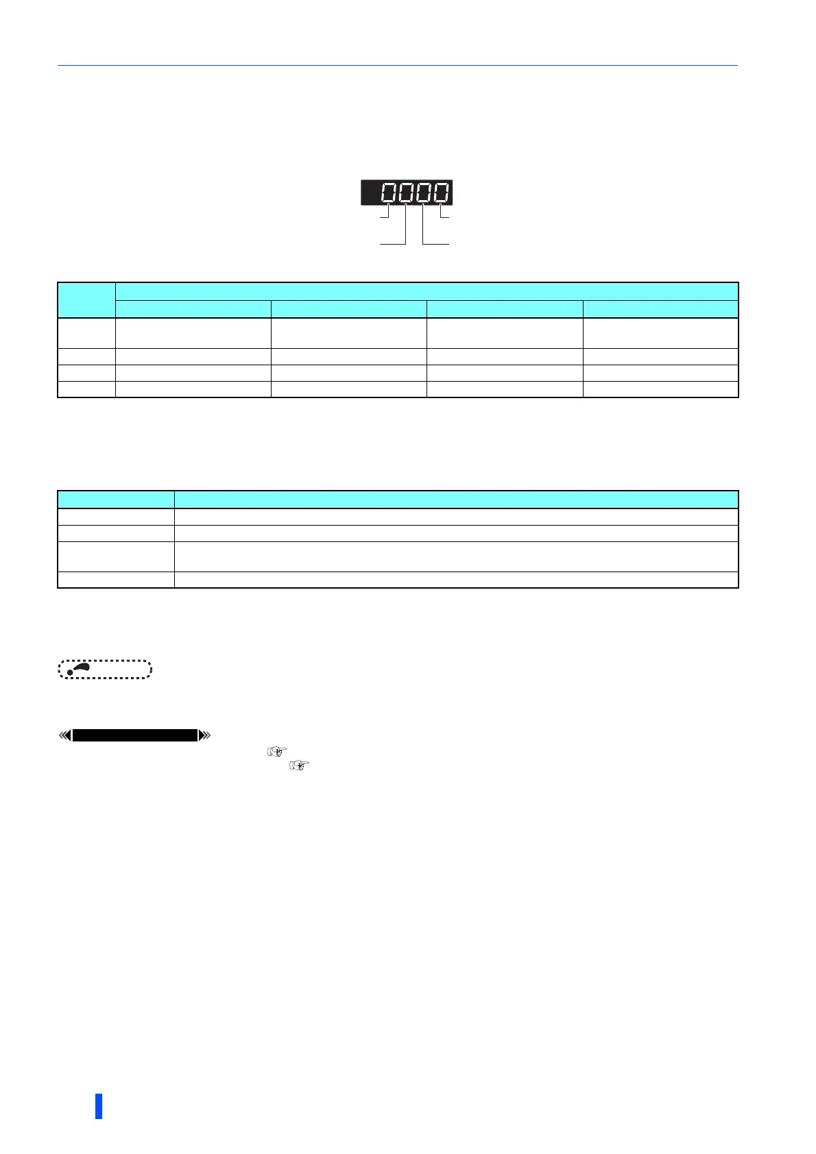
The "0(s)" to the left of the leftmost non-zero digit is(are) not shown in the monitor display.
For example, if no trace data is in internal RAM, the USB memory is not accessed, no trigger is detected, and the trace operation is performed,
"1" appears (not "0001").
• When copying the traced data to a USB memory device, the operating status of the USB host can be checked with the
inverter LED. For the overview of the USB communication function, refer to page 60.
• During trace operation, the trace status signal (Y40) can be output.
To use the Y40 signal, set "40 (positive logic) or 140 (negative logic)" in any of Pr.190 to Pr.196 (output terminal function
selection) to assign the function to the output terminal.
NOTE
• Changing the terminal assignment using Pr.190 to Pr.196 (output terminal function selection) may affect the other
functions. Set parameters after confirming the function of each terminal.
Pr.52 Operation panel main monitor selection page 359
Pr.178 to Pr.189 (input terminal function selection) page 430
Monitor
value
Trace status
1000s place 100s place 10s place 1s place
0 or no
display
No trace data in internal RAM USB memory not accessed Trigger not detected Trace stopped
1 Trace data in internal RAM USB memory being accessed Trigger detected Trace operation
2 — USB memory transfer error — —
3 — USB buffer overrun — —
LED status Operating status
OFF No USB connection.
ON The communication is established between the inverter and the USB device.
Flickering rapidly
Traced data is being transmitted. (In the memory mode, transmission command is being issued. In the recorder
mode, sampling is being performed.)
Flickering slowly Error in the USB connection.
1s place
Indicates trace operation.
10s place
Indicates trigger state.
1000s place
Indicates internal RAM state.
100s place
Indicates USB memory access state.

 Loading...


