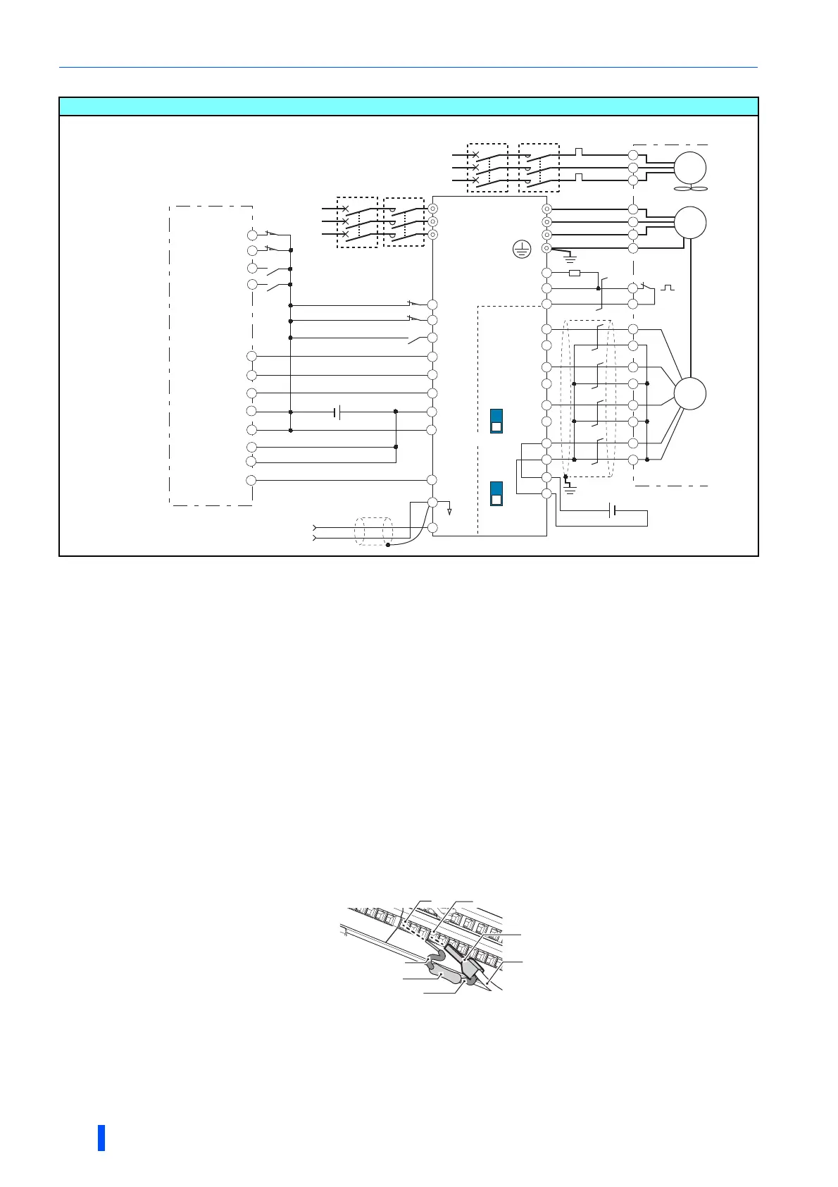
Connection of motor with encoder (vector control)
66
INSTALLATION AND WIRING
• Position control
Vector control dedicated motor (SF-V5RU, SF-THY), 12 V complementary
The pin number differs according to the encoder used.
Speed, control, torque control, and position control by pulse train input are available with or without the Z-phase
being connected.
Connect the encoder so that there is no looseness between the motor and motor shaft. Speed ratio must be 1:1.
Earth (ground) the shield of the encoder cable to the enclosure using a tool such as a P-clip. (Refer to page 67.)
For the complementary, set the terminating resistor selection switch to OFF position. (Refer to page 63.)
A separate power supply of 5 V/12 V/15 V/24 V is necessary according to the encoder power specification.
When the encoder output is the differential line driver type, only 5 V can be input.
Make the voltage of the external power supply the same as the encoder output voltage, and connect the external
power supply across PG and SD.
For terminal compatibility of the FR-JCBL, FR-V7CBL, and FR-A8AP, refer to page 65.
For the fan of the 7.5 kW or lower dedicated motor, the power supply is single phase. (200 V/50 Hz, 200 to 230 V/
60 Hz)
Connect the recommended 2 W 1 k resistor between the terminal PC and OH. (Recommended product:
MOS2C102J 2W1k by KOA Corporation) Insert the input line and the resistor to a 2-wire blade terminal, and
connect the blade terminal to the terminal OH. (For the recommended 2-wire blade terminals, refer to page 51.)
Insulate the lead wire of the resistor, for example by applying a contraction tube, and shape the wires so that the
resistor and its lead wire will not touch other cables. Caulk the lead wire securely together with the thermal protector
input line using a 2-wire blade terminal. (Do not subject the lead wire's bottom area to an excessive pressure.)
To use a terminal as the terminal OH, assign the OH (external thermal O/L relay input) signal to an input terminal.
(Set "7" in any of Pr.178 to Pr.189. For details, refer to page 430.)
Assign the function using Pr.178 to Pr.184, Pr.187 to Pr.189 (input terminal function selection).
When position control is selected, terminal JOG function is invalid and simple position pulse train input terminal
becomes valid.
Assign the function using Pr.190 to Pr.194 (output terminal function selection).
Torque limit command
(±10V)
1
5
(+)
(-)
Three-phase
AC power
supply
MCCB
R/L1
S/L2
T/L3
∗4 ∗6
∗3
PA1
FR-A8AP
PA2
PB1
PB2
PZ1
PZ2
PG
PG
SD
SD
Forward stroke end
Reverse stroke end
Pre-excitation/servo on
Clear signal
Pulse train
Sign signal
Preparation ready signal
STF
STR
LX
∗9
CLR ∗9
CLEAR
JOG
∗10
NP ∗9
∗1
Differential
line driver
Terminating
resistor
ON
OFF
SF-V5RU, SF-TH
U
V
W
U
A
B
C
V
W
E
G1
G2
A
Earth
(ground)
∗2
Three-phase
AC power supply
MCCB MC OCR
B
C
D
F
G
S
R
IM
FAN
PLG
External thermal protector
relay input
∗8
Thermal
protector
∗7
RH(OH)
SD
Inverter
Positioning unit
MELSEC-Q QD75P[ ]N/QD75P[ ]
MELSEC-L LD75P[ ]
PC
2W1kΩ
12VDC
power supply
(+)
(-)
∗5
PULSE F
PULSE R
PULSE COM
CLRCOM
RDYCOM
READY
PC
RDY ∗11
SE
FLS
RLS
DOG
STOP
COM
24VDC power supply
MC
Complementary
PC
Resistor (2 W1kΩ)
Insulate
Insulate
RH (OH)
To thermal protector
2-wire blade terminal
When OH signal is assigned to terminal RH
(Pr.182 = “7”)

 Loading...


