(M) Monitor display and monitor output signal
388
PARAMETERS
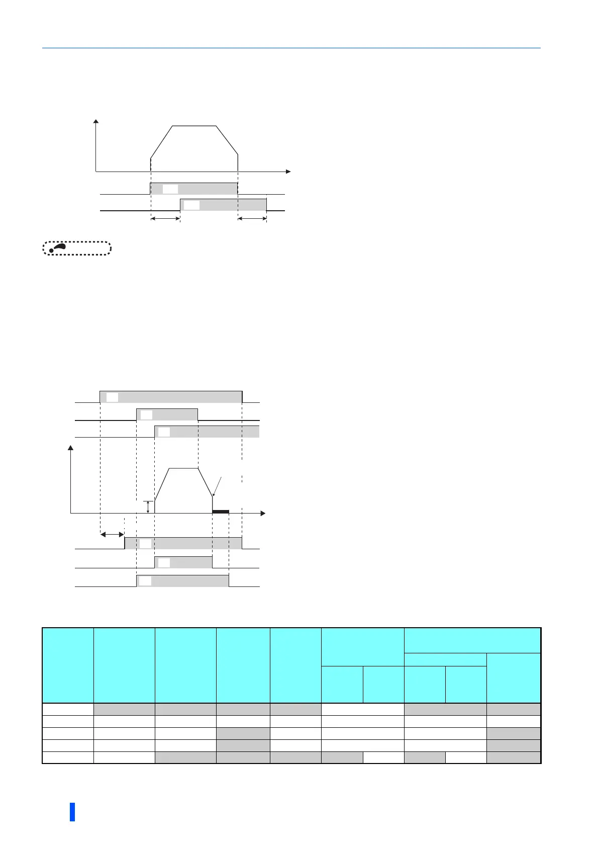
Adjusting the output terminal response level (Pr.289)
• The response level of the output terminals can be delayed in a range of 5 to 50 ms. (Operation example for the RUN
signal.)
NOTE
• When Pr.157 OL signal output timer is set for the Overload warning (OL) signal output, the OL signal is output when the set
time of (Pr.157 + Pr.289) elapses.
• For the output signal and the fault code output (on page 400) used in the PLC function (on page 545), the Pr.289 setting is
invalid (no filter).
Inverter operation ready signals (RY, RY2 signals) and inverter running
signals (RUN, RUN2, RUN3 signals)
• According to the inverter condition, the ON/OFF operation of each signal is as shown below.
Operation under V/F control and
Advanced magnetic flux vector control
• When the inverter is ready for operation, the Inverter
operation ready (RY) signal turns ON (stays ON during
operation.)
• When the inverter output frequency reaches Pr.13
Starting frequency or higher, the Inverter running (RUN,
RUN2) signals turn ON. The signal is OFF while the
inverter is stopped and during DC injection brake
operation.
• The Inverter running and start command is ON (RUN3)
signal is ON while the inverter is running or the start
signal is ON. (When the start command is ON, the RUN3
signal output turns ON even while the inverter's
protective function is activated or the MRS is ON.)
During DC injection brake operation as well, the output is
ON, and when the inverter stops, it turns OFF.
Output
signal
Start signal
OFF
(during
stop)
Start signal
ON
(during
stop)
Start
signal ON
(running)
DC
injection
brake
operation
Output shutoff
Automatic restart after
instantaneous power failure
Coasting
Restarting
Start
signal
ON
Start
signal
OFF
Start
signal
ON
Start
signal
OFF
RY ON ON ON ON OFF ON ON
RY2 OFF OFF OFF OFF OFF OFF OFF
RUN OFF OFF
ON OFF OFF OFF ON
RUN2 OFF OFF
ON OFF OFF OFF ON
RUN3 OFF
ON ON ON ON OFF ON OFF ON
OFF during power failure or undervoltage.
Output is shutoff in conditions like a fault and when the MRS signal is ON.
OFF while power is not supplied to the main circuit power supply.
Time
RUN
Pr.289 = 9999
ON
OFF
RUN
Pr.289 ≠ 9999
ON OFF
Pr.289 Pr.289
Output frequency
Power
supply
Output frequency
STF
RH
RY
RUN3
Reset
processing
Time
ON
ON
ON
ON
ON
ON
OFF
OFF
OFF
OFF
OFF
RUN
(RUN2)
DC injection brake
operation point
DC injection
brake
operation
Pr. 13

 Loading...


