(N) Operation via communication and its settings
PARAMETERS
577
5
GROUP
N
Operation command
The signal within parentheses ( ) is the initial status. The description changes depending on the setting of Pr.180 to Pr.184, Pr.187 (Input
terminal function selection) (page 430).
The inverter run enable signal is in the initial status for the separated converter type.
JOG operation/automatic restart after instantaneous power failure/start self-holding selection/reset cannot be controlled over a network, so in the
initial status bit8 to bit11 are invalid. To use bit8 to bit11, change the signal by Pr.185, Pr.186, Pr.188, or Pr.189 (Input terminal function
selection) (page 430) (A reset can be executed by the instruction code HFD.)
In RS-485 communication from the PU connector, only the forward rotation command and reverse rotation command can be used.
Inverter status monitor
The signal within parentheses ( ) is the initial status. The description changes depending on the setting of Pr.190 to Pr.196 (output terminal
function selection).
No function is assigned in the initial status for the separated converter type.
Item
Instruction
code
Bit
length
Description Example
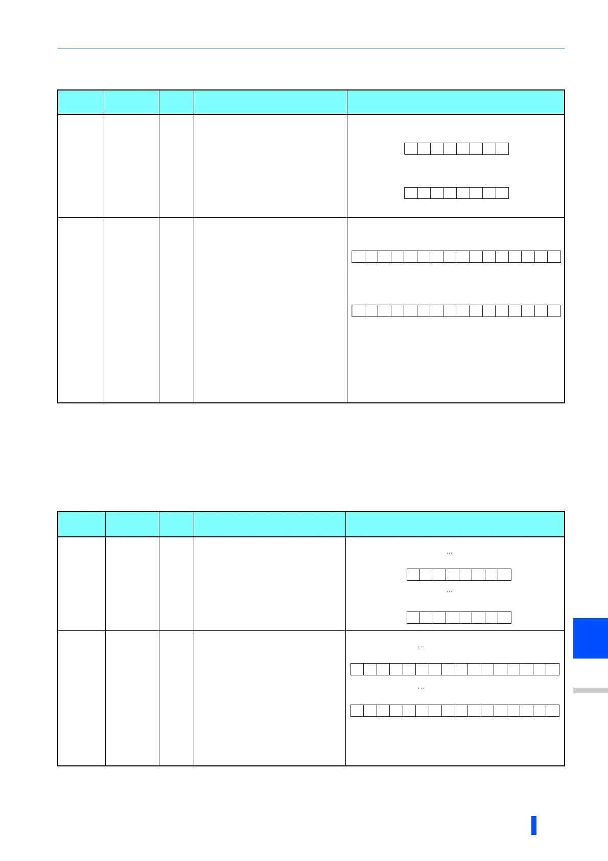
Operation
command
HFA 8 bits
b0: AU (Terminal 4 input selection)
b1: Forward rotation command
b2: Reverse rotation command
b3: RL (Low-speed operation command)
b4: RM (Middle-speed operation
command)
b5: RH (High-speed operation
command)
b6: RT (Second function selection)
b7: MRS (Output stop)
Operation
command
(extended)
HF9 16 bits
b0: AU (Terminal 4 input selection)
b1: Forward rotation command
b2: Reverse rotation command
b3: RL (
Low-speed operation command
)
b4: RM (Middle-speed operation
command)
b5: RH (High-speed operation
command)
b6: RT (Second function selection)
b7: MRS (Output stop)
b8: JOG (Jog operation selection)
b9: CS (Selection of automatic restart
after instantaneous power failure, flying
start)
b10: STP (STOP) (Start self-holding
selection)
b11: RES (Inverter reset)
b12 to b15: -
Item
Instruction
code
Bit
length
Description Example
Inverter
status
monitor
H7A 8 bits
b0: RUN (Inverter running)
b1: During forward rotation
b2: During reverse rotation
b3: SU (Up to frequency)
b4: OL (Overload warning)
b5: IPF (Instantaneous power failure/
undervoltage)
b6: FU (Output frequency detection)
b7: ABC1 (Fault)
Inverter
status
monitor
(extended)
H79 16 bits
b0: RUN (Inverter running)
b1: During forward rotation
b2: During reverse rotation
b3: SU (Up to frequency)
b4: OL (Overload warning)
b5: IPF (iInstantaneous power failure/
undervoltage)
b6: FU (Output frequency detection )
b7: ABC1 (Fault)
b8: ABC2 ()
b9: Safety monitor output
b10 to b14: -
b15: Fault occurrence
00000010
b7 b0
[Example 1] H02 Forward rotation
[Example 2] H00 Stop
00000000
b7 b0
00000010
b0
[Example 1] H0002 Forward rotation
00000000
b15
00000000
b0
[Example 2] H0800 low speed operation
(When Pr. 189 RES terminal function selection is set to "0")
00001000
b15
00000010
b7 b0
10000000
b7 b0
[Example 2] H80
[Example 1] H02
Stop at fault
occurrence
During forward
rotation
00000010
b0
00000000
b15
[Example 1] H0002 During forward rotation
10000000
b0
10000000
b15
[Example 2] H8080 Stop at fault occurrence

 Loading...


