Connection of stand-alone option units
INSTALLATION AND WIRING
75
2
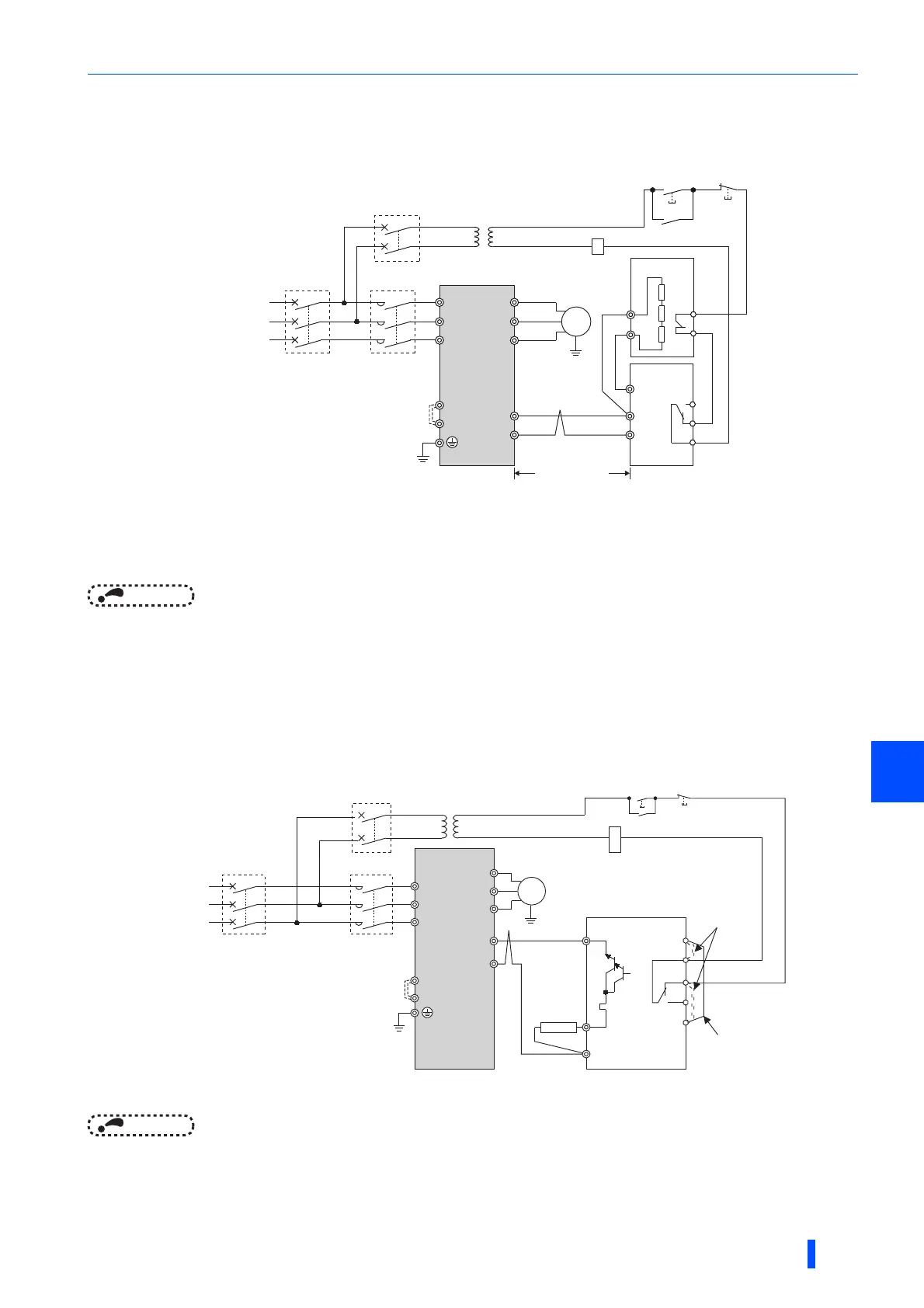
2.9.3 Connection of the brake unit (FR-BU)
Connect the brake unit (FR-BU2(H)) as shown below to improve the braking capability during deceleration.
The FR-BU is compatible with FR-A820-03160(55K) or lower and FR-A840-01800(55K) and lower.
When wiring, make sure to match the terminal symbol (P/+, N/-) at the inverter side and at the brake unit (FR-BU(H)) side. (Incorrect connection
will damage the inverter.)
When the power supply is 400 V class, install a stepdown transformer.
For the FR-A820-00490(7.5K) or lower and FR-A840-00250(7.5K) or lower, be sure to remove the jumper across terminals PR and PX.
The wiring distance between the inverter and brake unit (FR-BU2), and between the brake unit (FR-BU2) and discharging resistor must be within
5 m. Even when the cable is twisted, the wiring length must be within 10 m.
NOTE
• If the transistors in the brake unit should becomes faulty, the resistor will overheat. Install a magnetic contactor on the
inverter's input side and configure a circuit that shut off the current in case of a fault.
• Do not remove the jumper across terminals P/+ and P1 except when connecting a DC reactor (FR-HEL).
2.9.4 Connection of the brake unit (BU type)
Connect the brake unit (BU type) correctly as shown below. Incorrect connection will damage the inverter. Remove the
jumpers across terminals HB and PC and terminals TB and HC of the brake unit and fit one across terminals PC and TB.
The BU type is compatible with FR-A820-03160(55K) or lower and FR-A840-01800(55K) and lower.
When the power supply is 400 V class, install a stepdown transformer.
For the FR-A820-00490(7.5K) or lower and FR-A840-00250(7.5K) or lower, be sure to remove the jumper across terminals PR and PX.
NOTE
• The wiring distance between the inverter and brake unit (BU type), and between the brake unit (BU type) and discharging
resistor must be within 2 m. Even when the cable is twisted, the wiring length must be within 5 m.
• If the transistors in the brake unit should becomes faulty, the resistor will overheat and result in a fire. Install a magnetic
contactor on the inverter's input side and configure a circuit that shut off the current in case of a fault.
• Remove the jumper across terminals P/+ and P1 only when connecting a DC reactor (FR-HEL).
U
V
W
P/+
N/-
R/L1
S/L2
T/L3
Motor
M
Inverter
10 m or less
PR
N/-
P/+
P
HA
HB
HC
FR-BU
FR-BR
TH2
TH1
PR
Three-phase AC
power supply
MCCB
MC
MC
OFFON
MC
T ∗2
∗1
PR
PX
∗4
∗3
U
V
W
Motor
M
Inverter
Brake unit
(BU type)
Discharging
resistor
R/L1
S/L2
T/L3
N/-
P/+
Three-phase
AC power
supply
MCCB
MC
P
PR
OCR
N
Fit a jumper
Remove the
jumper
HC
HB
HA
TB
OCR
PC
MC
OFFON
MC
T ∗1
PR
PX
∗2

 Loading...


