(N) Operation via communication and its settings
PARAMETERS
555
5
GROUP
N
5.15 (N) Operation via communication and its
settings
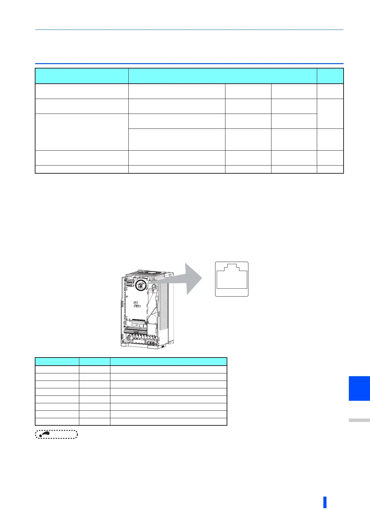
5.15.1 Wiring and configuration of PU connector
Using the PU connector enables communication operation from a personal computer, etc.
When the PU connector is connected with a personal, FA or other computer by a communication cable, a user program can
run and monitor the inverter or read and write to parameters.
PU connector pin-outs
NOTE
• Pins No. 2 and 8 provide power to the operation panel or parameter unit. Do not use these pins during RS-485
communication.
• Do not connect the PU connector to the computer's LAN board, FAX modem socket or telephone modular connector. The
product could be damaged due to differences in electrical specifications.
Purpose Parameter to set
Refer to
page
To start operation via
communication
Initial setting of operation via
communication
P.N000, P.N001,
P.N013, P.N014
Pr.549, Pr.342,
Pr.502, Pr.779
560
To operate via communication
from PU connector
Initial setting of computer link
communication (PU connector)
P.N020 to
P. N 02 8
Pr.117 to Pr.124
563
To operate via communication
from RS-485 terminals
Initial setting of computer link
communication (RS-485 terminals)
P.N030 to
P. N 03 8
Pr.331 to
Pr.337, Pr.341
Modbus-RTU communication
specification
P.N002, P.N030,
P.N031, P.N034,
P.N080,
Pr.539, Pr.331,
Pr.332, Pr.334,
Pr.343,
579
To Communicate using USB (FR
Configurator2)
USB communication P.N040, P.N041 Pr.547, Pr.548 563
To connect a GOT GOT automatic recognition P.N020, P.N030 Pr.117, Pr.331 595
Pin number Name Description
1 SG Earth (ground) (connected to terminal 5)
2 Operation panel power supply
3 RDA Inverter receive+
4 SDB Inverter send-
5 SDA Inverter send+
6 RDB Inverter receive-
7 SG Earth (ground) (connected to terminal 5)
8 Operation panel power supply
Inverter
(Receptacle side)
Front view
81to

 Loading...


