(D) Operation command and frequency command
PARAMETERS
325
5
GROUP
D
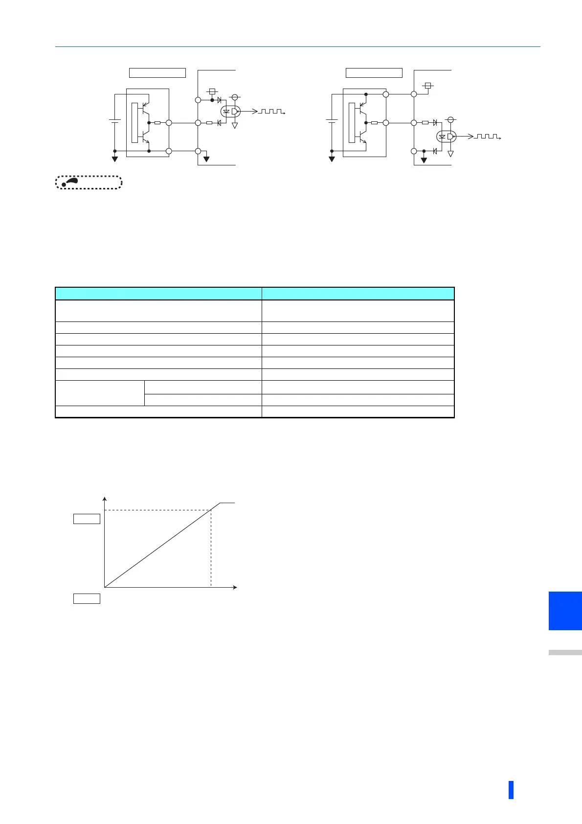
• Connection with a complementary output system pulse generator
NOTE
• When pulse train input is selected, the function assigned to terminal JOG by Pr.185 JOG terminal function selection is
invalid.
• When "2" (simple position pulse train command by pulse train input) is set to Pr.419 Position command source selection,
the JOG terminal becomes the simple position pulse train terminal regarding of the Pr.291 setting.
• Pr.291 is the selection parameter for pulse train output/FM output. Thus, before changing the setting, check the specifications
of the device connected to the terminal FM. (For the pulse train output, refer to page 373.)
Pulse train input specification
The wiring length of complementary output is dependent on the output wiring specification of the complementary output unit. The stray
capacitance of the wiring changes considerably according to how the cable is laid, thus the maximum wiring length is not a guaranteed value.
Adjustment of pulse train and frequency (Pr.385, Pr.386)
• The frequency during zero input pulse and maximum input pulse can be set with Pr.385 Frequency for zero input pulse
and Pr.386 Frequency for maximum input pulse, respectively.
Limit value = (Pr.386 - Pr.385) 1.1 + Pr.385
How to calculate the input pulse division scaling factor (Pr.384)
• The maximum number of pulses can be calculated by the following formula with Pr.384Input pulse division scaling
factor:
Maximum number of pulses (pulse/s) = Pr.384 400 (maximum 100k pulses/s)
(number of detectable pulses = 11.45 pulses/s)
• For example, to run the invert at 0 Hz when pulse train input is zero and at 30 Hz when pulse train is 4000 pulses/sec, set
the inverter as follows:
Pr.384 = 10 (maximum number of input pulses 4000 pulses/s)
Pr.385 = 0 Hz, Pr.386 = 30 Hz (pulse train limit value 33 Hz)
Item Specification
Supported pulse method
Open collector output.
Complementary output. (24 V power supply voltage)
HIGH input level 20 V or more (voltage between JOG and SD)
LOW input level 5 V or less (voltage between JOG and SD)
Maximum input pulse rate 100 kpps
Minimum input pulse width 2.5 us
Input resistance/load current 2 k (typ)/10 mA (typ)
Maximum wiring length
(reference value)
Open collector output method
10 m (0.75 mm
2
/twisted pair)
Complementary output method 100 m (output resistance 50 )
Detection resolution 1/3750
JOG
PC
SD
Sink logic
Inverter
2kΩ
24V power
Source logic
24V power
JOG
PC
SD
Inverter
2kΩ
60Hz(50Hz)
Pr. 386
0Hz
Maximum input pulse
Limit value
Input pulse
(pulse/s)
(Hz)
Output
frequency
0
Pr. 385

 Loading...


