(T) Multi-Function Input Terminal Parameters
432
PARAMETERS
When Pr.59 Remote function selection "0", functions of the RL, RM, and RH signals will be changed as in the table.
When Pr.270 Stop-on contact/load torque high-speed frequency control selection = "1, 3, 11, or 13", functions of the RL and RT signals will
be changed as in the table.
OH signal will operate with the relay contact "open".
When stop position is to be input from external for orientation control, FR-A8AX (16-bit digital input) is required.
Servo ON is enabled during the position control.
Available when the plug-in option is connected. For details, refer to the Instruction Manual of the option.
The setting is available only for standard models and IP55 compatible models.
NOTE
• Same function can be assigned to two or more terminals. In this case, the logic of terminal input is OR.
• Priority of the speed command is JOG > multi-speed setting (RH, RM, RL, REX) > PID (X14).
• When the (X10) signal is not set up, Pr.79 Operation mode selection = "7", and PU operation external interlock (X12) signal
is Inverter run enable signal.
• Same signal is used to assign multi-speed (7 speed) and remote setting. Setting cannot be performed individually.
• When the Load pattern selection forward/reverse rotation boost (X17) signal is not assigned, RT signal will share this
function.
• If Pr.419= "2" (simple pulse train position command) is set, the terminal JOG is used for the simple position pulse train input
regardless of the Pr.291 Pulse train I/O selection pulse train input/output selection setting.
• When the terminal assignment is changed using Pr.178 to Pr.189 (input terminal function selection), the terminal name
will be different, which may result in an error of wiring, or affect other functions. Set parameters after confirming the function
of each terminal.
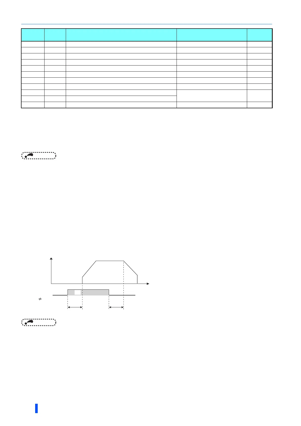
Adjusting the response of input terminal (Pr.699)
• Response of the input terminal can be delayed in a range between 5 to 50 ms. (Example of STF signal operation)
NOTE
• Setting of Pr.699 is disabled (no filter) in the following cases.
- Input terminal is already turned ON when the power is turned ON
- Input signal used for the PLC function
- Inverter run enable signal (X10) signal, Simple position pulse train sign (NP) signal, Simple position droop pulse clear (CLR)
signal
77 X77 Pre-charge end command Pr.760 to Pr.764 517
78 X78 Second pre-charge end command Pr.765 to Pr.769 517
79 X79 Second PID forward/reverse action switchover Pr.753 to Pr.758 501
80 X80 Second PID control valid terminal Pr.753 to Pr.758 501
87 X87 Sudden stop Pr.464 to Pr.494 232
92 X92 Emergency stop Pr.1103 285
93 X93 Torque limit selection Pr.1113 219
94 X94 Control signal input for main circuit power supply MC Pr.30, Pr.137, Pr.248, Pr.254 470
95 X95 Converter unit fault input
Pr.57, Pr.58, Pr.135 to Pr.139,
Pr.159
464
96 X96 Converter unit fault (E.OHT, E.CPU) input
9999 ——— No function ———— ————
Setting
Signal
name
Function Related parameter
Refer to
page
Time
ON
OFF
STF
Pr.699 9999
Pr.699 Pr.699
Output frequency

 Loading...


