Control circuit
54
INSTALLATION AND WIRING
2.6.5 When using separate power supplies for the
control circuit and the main circuit
Cable size for the control circuit power supply (terminals R1/L11 and S1/
L21)
• Terminal screw size: M4
• Cable gauge: 0.75 mm
2
to 2 mm
2
• Tightening torque: 1.5 N·m
Connection method
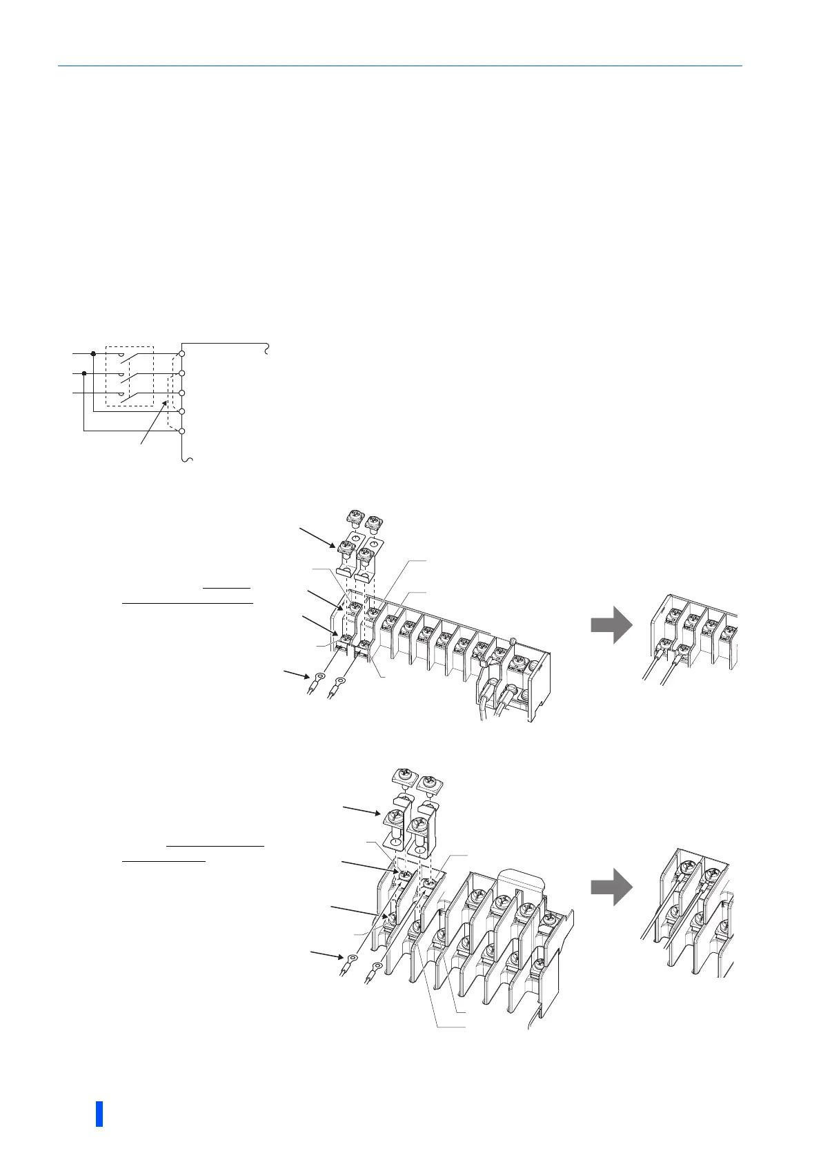
• FR-A820-00250(3.7K) or lower, FR-A840-00126(3.7K) or lower
• FR-A820-00340(5.5K) to FR-A820-00630(11K), FR-A840-00170(5.5K) to FR-A840-00380(15K)
<Connection diagram> When a fault occurs, opening of the electromagnetic contactor (MC) on the
inverter power supply side results in power loss in the control circuit, disabling the
fault output signal retention. Terminals R1/L11 and S1/L21 are provided to hold a
fault signal. In this case, connect the power supply terminals R1/L11 and S1/L21
of the control circuit to the input side of the MC.
Do not connect the power cable to incorrect terminals. Doing so may damage the
inverter.
(a) Remove the upper screws.
(b) Remove the lower screws.
(c) Remove the jumper.
(d) Connect the separate
power supply cable for the
control circuit to the lower
terminals (R1/L11, S1/L21).
(a) Remove the upper screws.
(b) Remove the lower screws.
(c) Remove the jumper.
(d) Connect the separate power
supply cable for the control
circuit to the upper terminals
(R1/L11, S1/L21).
Inverter
MC
R/L1
S/L2
T/L3
R1/L11
S1/L21
Remove the jumper
Main circuit terminal block
(c)
(a)
(b)
(d)
T/L3
S/L2
R/L1
S1/L21
R1/L11
Main circuit terminal block
(c)
(d)
(a)
T/L3
S/L2
R/L1
S1/L21
R1/L11
(b)

 Loading...


