Installation of the inverter and enclosure design
32
INSTALLATION AND WIRING
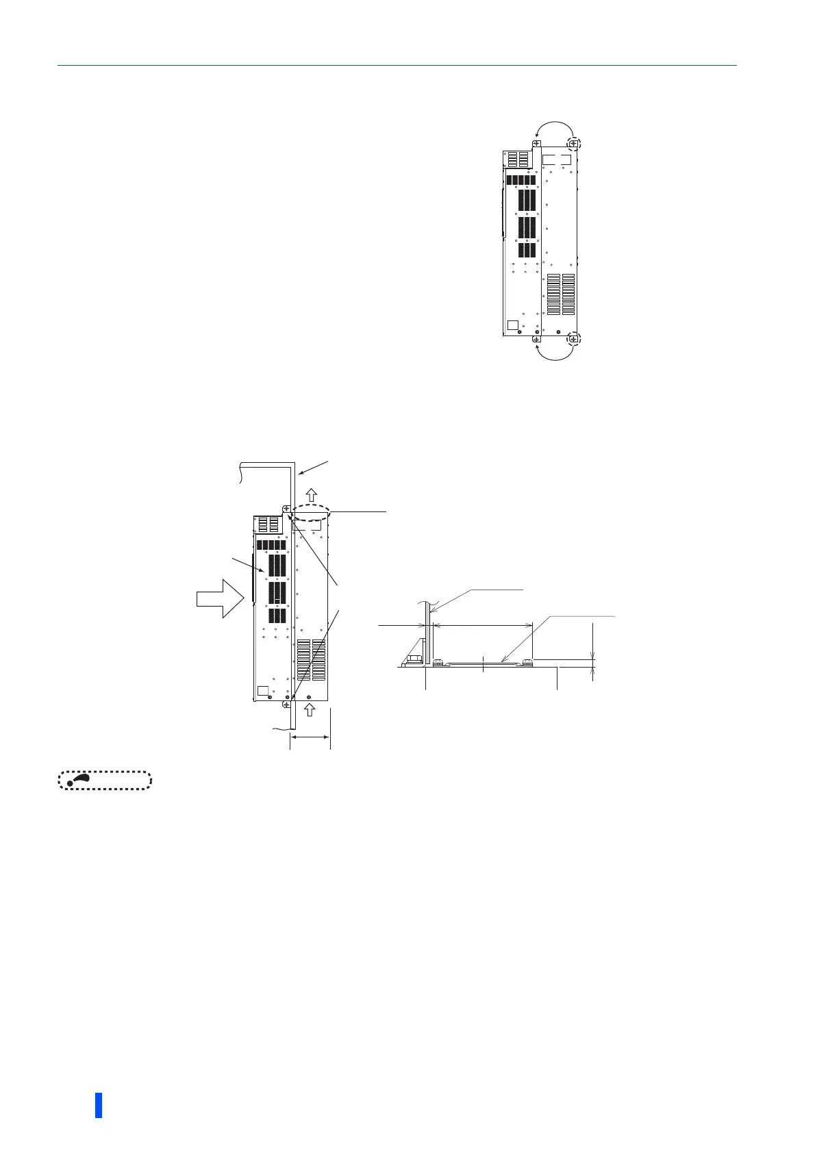
Shift and removal of a rear side installation frame
Installation of the inverter
Push the inverter heatsink portion outside the enclosure and fix the enclosure and inverter with upper and lower
installation frame.
NOTE
• Having a cooling fan, the cooling section which comes out of the enclosure cannot be used in the environment of water drops,
oil, mist, dust, etc.
• Be careful not to drop screws, dust etc. into the inverter and cooling fan section.
One installation frame is attached to each of the upper and lower
parts of the inverter. Change the position of the rear side
installation frame on the upper and lower sides of the inverter to
the front side as shown on the right. When changing the installation
frames, make sure that the installation orientation is correct.
Upper
installation
frame
Lower
installation
frame
Shift
Shift
Inverter/
Converter unit
Inside the
enclosure
Enclosure
Exhausted air
Installation
frame
Dimension of
the outside of
the enclosure
Cooling
wind
Enclosure
There are finger guards behind the enclosure.
Therefore, the thickness of the panel should be
less than 10 mm (∗1) and also do not place
anything around finger guards to avoid contact
with the finger guards.
Finger guard
140mm
6mm
10mm∗1
185mm

 Loading...


