(A) Application parameters
PARAMETERS
527
5
GROUP
A
Adjustment procedure for dancer roll position detection signal
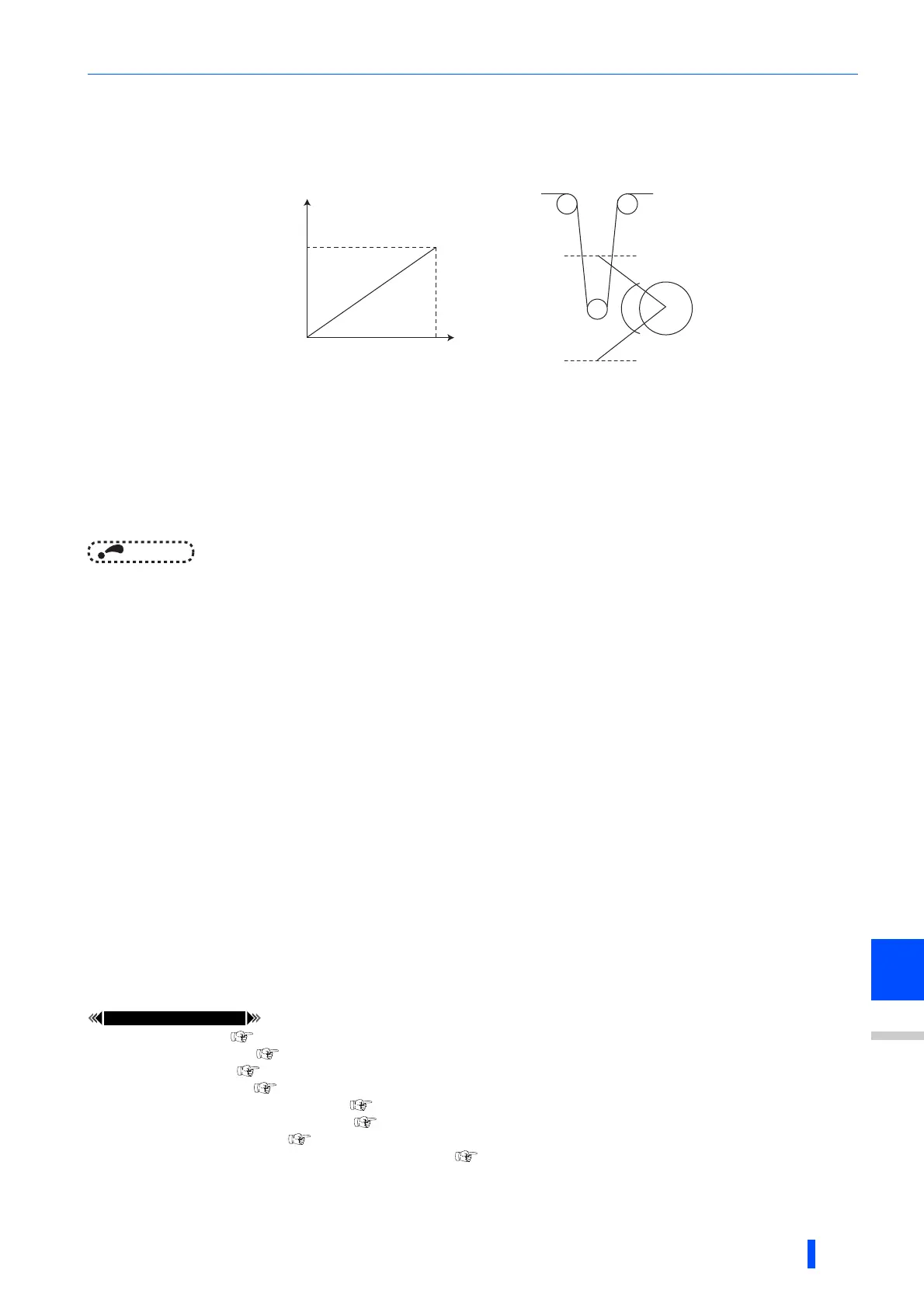
• When the input of terminal 4 is voltage input, 0 V and 5 V (10 V) are the lower limit position and upper limit position,
respectively. When it is current input, 4 mA and 20 mA are the lower limit position and upper limit position, respectively.
(initial value) When the potentiometer has an output of 0 to 7 V, C7 (Pr.905) must be calibrated at 7 V.
(Example) To execute control at the dancer center position using a 0 to 7 V potentiometer
1) Switch the current/voltage input selection switch to "OFF", set "2" to Pr.267 and set terminal 4 input to voltage input.
2) Input 0 V across terminals 4 and 5, and calibrate C6 (Pr.904). (The % display that is indicated at analog calibration is not
related to the % of the feedback value.)
3) Input 7 V across terminals 4 and 5, and calibrate C6 (Pr.905). (The % display that is indicated at analog calibration is not
related to the % of the feedback value.)
4) Set Pr.133 to "50%".
NOTE
• After changing the Pr.267 setting, check the voltage/current input selection switch. Incorrect setting may cause a fault, failure
or malfunction. (Refer to page 406 for the setting.)
• If the RH, RM, RL, or REX signal (multi-speed operation), or JOG signal is input in regular PID control, PID control is
interrupted. However, at dancer control, these signals are treated as main speed commands, so PID control is continued.
• During dancer control, Pr.44 and Pr.45 Second deceleration time is the parameter for setting the acceleration/deceleration
time for the main speed command. This function does not function as a second function.
• When the switchover mode is set by setting "6" to Pr.79, dancer control (PID control) is invalid.
• When dancer control is selected, the speed command of terminal 4 by the AU signal is invalid.
• The acceleration/deceleration action of the main speed command is the same as that when the frequency is increased or
decrease by analog input. For this reason,
• The SU signal sometimes stays ON even if operation is turned ON/OFF by the start signal. (The constant-speed status is
maintained.)
• The DC brake operation start frequency when the start signal is turned OFF is not Pr.10 but the smaller value between Pr.13
and 0.5 Hz.
• The set frequency monitor is the value "main speed command + PID control" which is constantly changing.
• With the main speed setting frequency setting, acceleration/deceleration is performed for the acceleration/deceleration time
set at Pr.44 and Pr.45, and with the output frequency setting, acceleration/deceleration is performed for the acceleration/
deceleration time set at Pr.7 and Pr.8. For this reason, with the output frequency, when the time set at Pr.7 and Pr.8 is longer
than the time set at Pr.44 and Pr.45, acceleration/deceleration is performed for the acceleration/deceleration time set at Pr.7
and Pr.8.
• The limit of the integral term is the smaller of 100% and the value after conversion of the straight line after interpolation of Pr.1
Maximum frequency by Pr.902 and Pr.903 to the PID manipulated amount. Note, however, that the lower limit frequency
limits the output frequency, but does not restrict the action of the integral item.
Pr.57 Restart coasting time page 528
Pr.59 Remote function selection page 295
Pr.73 Analog input selection page 406
Pr.79 Operation mode selection page 306
Pr.178 to Pr.189 (input terminal function selection) page 430
Pr.190 to Pr.196 (output terminal function selection) page 384
Pr.561 PTC thermistor protection level page 331
C2 (Pr.902) to C7 (Pr.905) Frequency setting voltage (current) bias/gain page 415
5V(10V)
0V
20mA
4mA
0%
Feedback value
Potentiometer, etc.
Lower limit
position
Upper limit
position
100%

 Loading...


