Control circuit
INSTALLATION AND WIRING
45
2
2.6 Control circuit
2.6.1 Details on the control circuit terminals
Input signal function of the terminals in can be selected by setting Pr.178 to Pr.196 (I/O terminal function selection).
(Refer to page 430.)
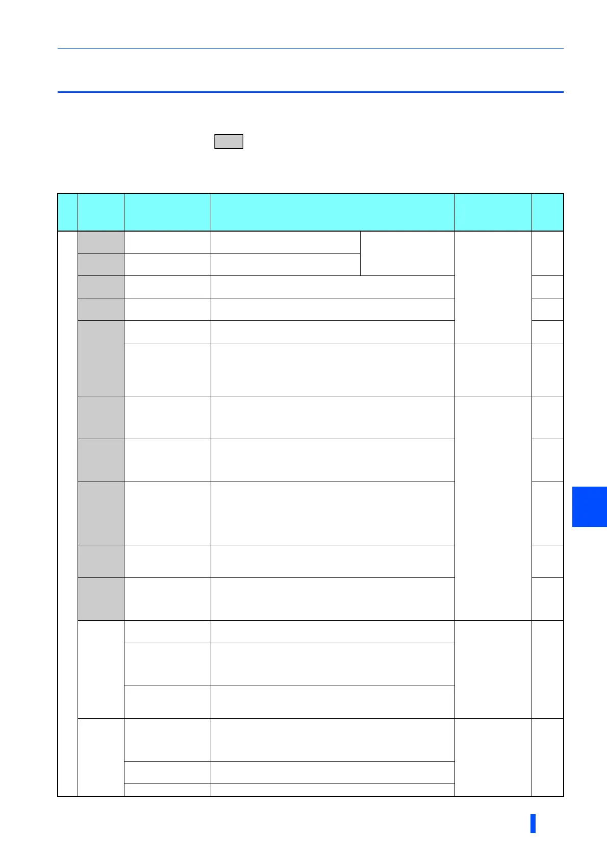
Input signal
Type
Terminal
Symbol
Terminal name Terminal function description
Rated
specification
Refer
to
page
Contact input
STF Forward rotation start
Turn ON the STF signal to start forward
rotation and turn it OFF to stop.
When the STF and
STR signals are turned
ON simultaneously, the
stop command is given.
Input resistance
4.7 k
Voltage when
contacts are open:
21 to 27 VDC
When contacts are
short-circuited: 4 to
6 mADC
436
STR Reverse rotation start
Turn ON the STR signal to start
reverse rotation and turn it OFF to stop.
STP
(STOP)
Start self-holding
selection
Turn ON the STP (STOP) signal to self-hold the start signal. 436
RH, RM,
RL
Multi-speed selection
Multi-speed can be selected according to the combination of RH,
RM and RL signals.
328
JOG
Jog mode selection
Turn ON the JOG signal to enable JOG operation (initial setting)
and turn ON the start signal (STF or STR) to start JOG operation.
327
Pulse train input
Terminal JOG is also used as a pulse train input terminal. To use
as a pulse train input terminal, change the Pr.291 setting.
(maximum input pulse: 100k pulses/s)
Input resistance 2
k
When contacts are
short-circuited: 8 to
13 mADC
324
RT
Second function
selection
Turn ON the RT signal to enable the second function.
When the second function such as "second torque boost" and
"second V/F (base frequency)" is set, turning ON the RT signal
enables the selected function.
Input resistance
4.7 k
Voltage when
contacts are open:
21 to 27 VDC
When contacts are
short-circuited: 4 to
6 mADC
434
MRS Output stop
Turn ON the MRS signal (20 ms or more) to stop the inverter
output.
Use this signal to shut off the inverter output when stopping the
motor with an electromagnetic brake.
433
RES Reset
Use this signal to reset a fault output provided when a protective
function is activated. Turn ON the RES signal for 0.1 s or longer,
then turn it OFF.
In the initial setting, reset is set always-enabled. By setting Pr.75,
reset can be set enabled only at fault occurrence. The inverter
recovers about 1 s after the reset is released.
259
AU
Terminal 4 input
selection
The terminal 4 function is available only when the AU signal is
turned ON.
Turning the AU signal ON makes terminal 2 invalid.
406
CS
Selection of
automatic restart
after instantaneous
power failure
When the CS signal is left ON, the inverter restarts automatically
at power restoration. Note that restart setting is necessary for this
operation. In the initial setting, a restart is disabled.
528,
534
SD
Contact input
common (sink)
Common terminal for the contact input terminal (sink logic),
terminal FM.
——
External transistor
common (source)
Connect this terminal to the power supply common terminal of a
transistor output (open collector output) device, such as a
programmable controller, in the source logic to avoid malfunction
by undesirable current.
24 VDC power supply
common
Common terminal for the 24 VDC power supply (terminal PC,
terminal +24)
Isolated from terminals 5 and SE.
PC
External transistor
common (sink)
Connect this terminal to the power supply common terminal of a
transistor output (open collector output) device, such as a
programmable controller, in the sink logic to avoid malfunction by
undesirable currents.
Power supply
voltage range 19.2
to 28.8 VDC
Permissible load
current 100 mA
50
Contact input
common (source)
Common terminal for contact input terminal (source logic).
24 VDC power supply Can be used as a 24 VDC 0.1 A power supply.

 Loading...


