(M) Monitor display and monitor output signal
384
PARAMETERS
5.11.6 Output terminal function selection
The initial value is for standard models and IP55 compatible models.
The initial value is for separated converter types.
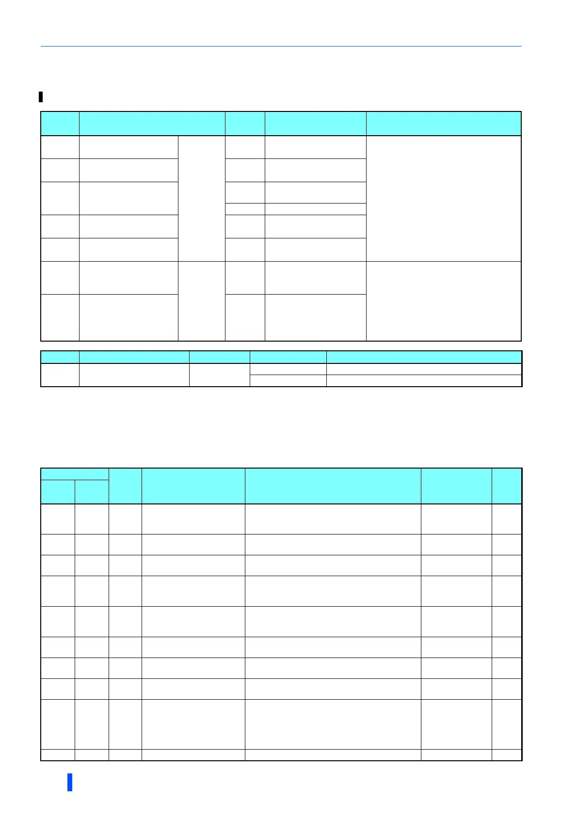
Output signal list
• The functions of the output terminals can be set.
• Refer to the following table and set each parameter. (0 to 99: Positive logic, 100 to 199: Negative logic)
Use the following parameters to change the functions of the open collector output terminals and relay output terminals.
Pr. Name
Initial
value
Initial set signal Setting range
190
M400
RUN terminal
function selection
Open
collector
output
terminal
0 RUN (Inverter running)
0 to 8, 10 to 20, 22, 25 to 28, 30 to 36,
38 to 54, 56, 57, 60, 61, 63, 64, 67, 68, 70,
79, 84, 85, 90 to 99, 100 to 108,
110 to 116, 120, 122, 125 to 128,
130 to 136, 138 to 154, 156, 157, 160, 161,
163, 164, 167, 168, 170, 179, 184, 185,
190 to 199, 200 to 208, 300 to 308, 9999
191
M401
SU terminal function
selection
1 SU (Up to frequency)
192
M402
IPF terminal function
selection
2
IPF (Instantaneous power
failure/undervoltage)
9999
No function
193
M403
OL terminal function
selection
3 OL (Overload warning)
194
M404
FU terminal function
selection
4
FU (Output frequency
detection)
195
M405
ABC1 terminal
function selection
Relay
output
terminal
99 ALM (Fault)
0 to 8, 10 to 20, 22, 25 to 28, 30 to 36,
38 to 54, 56, 57, 60, 61, 63, 64, 67, 68, 70,
79, 84, 85, 90, 91, 94 to 99, 100 to 108,
110 to 116, 120, 122, 125 to 128,
130 to 136, 138 to 154, 156, 157, 160, 161,
163, 164, 167, 168, 170, 179, 184, 185,
190, 191, 194 to 199, 200 to 208,
300 to 308, 9999
196
M406
ABC2 terminal
function selection
9999 No function
Pr. Name Initial value Setting range Description
289
M431
Inverter output terminal
filter
9999
5 to 50 ms Set the time delay for the output terminal response.
9999 No output terminal filter.
Setting
Signal
name
Function Operation
Related
parameter
Refer
to
page
Positive
logic
Negative
logic
0 100 RUN Inverter running
Output during operation when the inverter output
frequency reaches Pr.13 Starting frequency or
higher.
388
1 101 SU Up to frequency
Output when the output frequency reaches the set
frequency.
Pr.41 392
2 102 IPF
Instantaneous power failure/
undervoltage
Output when an instantaneous power failure or
undervoltage protection operation occurs.
Pr.57
528,
534
3 103 OL Overload warning
Output during operation of the stall prevention
function.
Pr.22, Pr.23, Pr.66,
Pr.148, Pr.149,
Pr.154
348
4 104 FU Output frequency detection
Output when the output frequency reaches the
frequency set in Pr.42 (Pr.43 during reverse
rotation) or higher.
Pr.42, Pr.43 392
5 105 FU2
Second output frequency
detection
Output when the output frequency reaches the
frequency set in Pr.50 or higher.
Pr.50 392
6 106 FU3
Third output frequency
detection
Output when the output frequency reaches the
frequency set in Pr.116 or higher.
Pr.116 392
7 107 RBP
Regenerative brake pre-
alarm
Output when 85% of the regenerative brake duty
set in Pr.70 is reached.
Pr.70 614
8 108 THP
Electronic thermal O/L relay
pre-alarm
Output when the cumulative electronic thermal O/
L relay value reaches 85% of the trip level.
(Electronic thermal O/L relay protection (E.THT/
E.THM) is activated when the value reaches
100%.)
Pr.9 331
10 110 PU PU operation mode Output when PU operation mode is selected. Pr.79 306

 Loading...


