Communication connectors and terminals
INSTALLATION AND WIRING
59
2
2.7 Communication connectors and terminals
2.7.1 PU connector
Mounting the operation panel or the parameter unit on the enclosure
surface
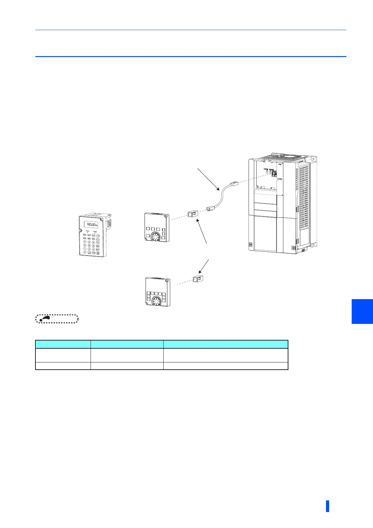
• Having an operation panel or a parameter unit on the enclosure surface is convenient. With a connection cable, the
operation panel or the parameter unit can be mounted to the enclosure surface and connected to the inverter.
Use the option FR-CB2[ ], or connectors and cables available on the market.
(To mount the operation panel, the optional connector (FR-ADP) is required.)
Securely insert one end of the connection cable until the stoppers are fixed.
NOTE
• Refer to the following table when fabricating the cable on the user side. Keep the total cable length within 20 m.
• Commercially available products (as of November 2013)
Communication operation
• Using the PU connector enables communication operation from a personal computer, etc. When the PU connector is
connected with a personal, FA or other computer by a communication cable, a user program can run to monitor the inverter
or read and write parameters.
Communication can be performed with the Mitsubishi inverter protocol (computer link operation).
For the details, refer to page 555.
Name Model Manufacturer
Communication cable
SGLPEV-T (Cat5e/300 m)
24AWG 4P
Mitsubishi Cable Industries, Ltd.
RJ-45 connector 5-554720-3 Tyco Electronics
Parameter unit connection cable
(FR-CB2[ ]) (option)
Operation panel (FR-DU08)
Parameter unit (FR-PU07)
(option)
Operation panel connection
connector (FR-ADP)
(option)
STF FWD PU
Operation panel (FR-LU08)
(option)

 Loading...


