(A) Application parameters
466
PARAMETERS
Be careful of the capacity of the sequence output terminals.
The applied terminals differ by the settings of Pr.190 to Pr.196 (output terminal function selection).
When connecting a DC power supply, insert a protective diode.
When connecting an AC power supply, use the relay output option (FR-A8AR) and use contact outputs.
The applied terminals differ by the settings of Pr.180 to Pr.189 (input terminal function selection).
To use the signal, assign the function to the output terminal Pr.190 to Pr.195 (output terminal function selection) of the converter unit. Always
set the negative logic for the ALM signal.
NOTE
• Use the electronic bypass function in External operation mode. In addition, the wiring terminals R1/L11 and S1/L21 must be
connected to a separate power source that does go through MC1. Be sure to connect using a separate power supply.
•
Be sure to provide a mechanical interlock for MC2 and MC3.
• Operation of magnetic contactor (MC1, MC2, MC3)
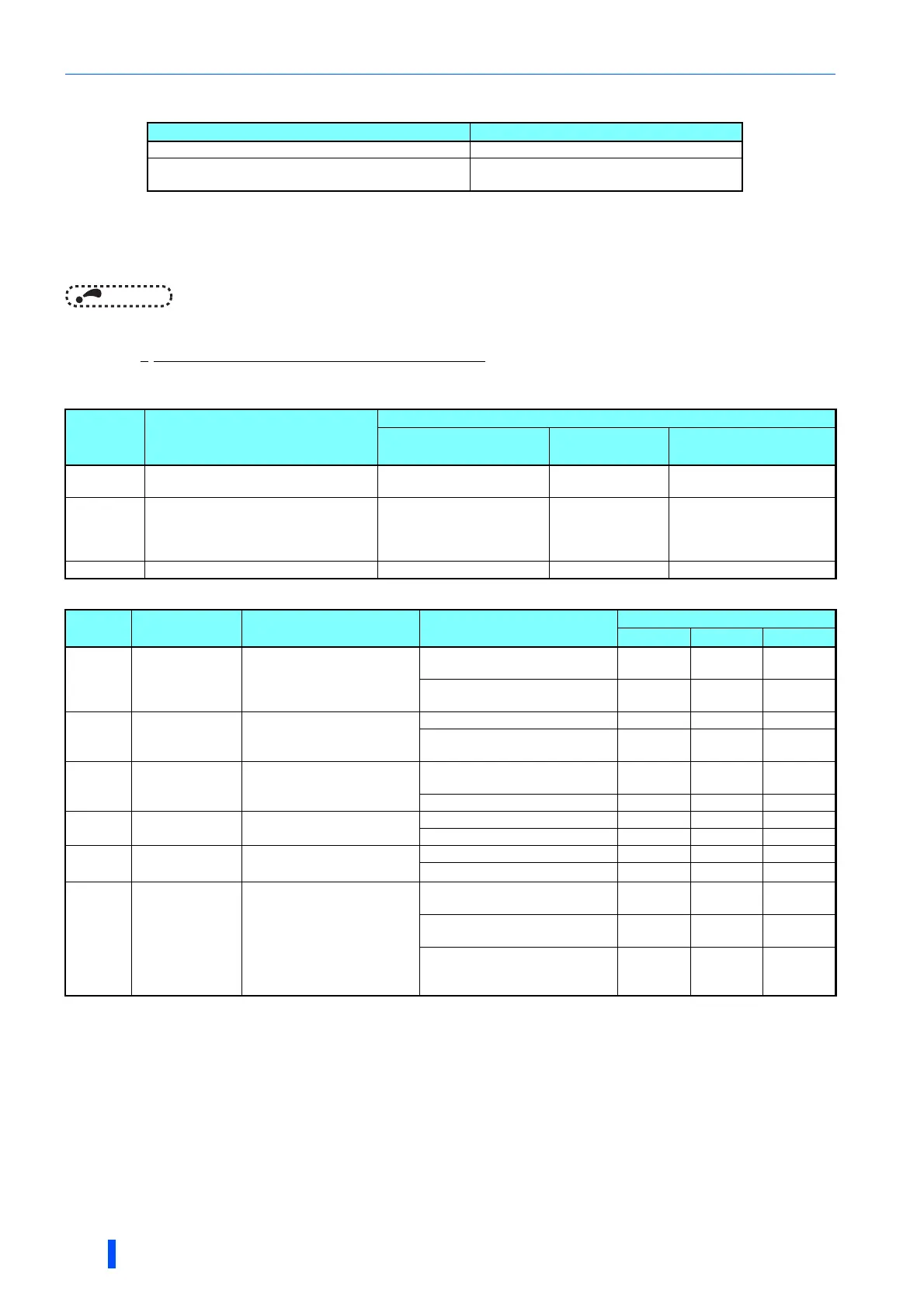
• The input signals are as shown below.
Magnetic
contactor
Installation location
Operation
During commercial
power supply operation
During inverter
operation
During inverter fault
MC1
Between power supply and inverter
input side
Shorted Shorted
Open
(short by reset)
MC2 Between power supply and motor Shorted Open
Open
(Selected by Pr.138. Always
open when the external
thermal relay is operating.)
MC3 Between inverter output side and motor Open Shorted Open
Signal
Applied
terminal
Function Operation
MC operation
MC1 MC2 MC3
MRS MRS
Selects whether or not
operation is available.
ON Electronic bypass operation
available
--
OFF Electronic bypass operation
not available
Invariance
CS CS
Inverter/commercial power
supply operation switchover
ON Inverter operation
OFF Commercial power supply
operation
STF
(STR)
STF
(STR)
Inverter operation command
(Disabled during commercial
power supply operation)
ON Forward rotation (reverse
rotation)
OFF Stop
OH
Set one of Pr.180
to Pr.189 to "7".
External thermal relay input
ON Motor normal --
OFF Motor fault
RES RES Operation status reset
ON Reset Invariance Invariance
OFF
Normal operation
--
X95/X96
Set "95" and "96"
in any of Pr.180
to Pr.189.
Converter unit fault /
Converter unit fault (E.OHT,
E.CPU)
X95 signal OFF, X96 signal OFF
Converter fault (E.OHT, E.CPU)
X95 signal ON, X96 signal ON
Converter normal
--
X95 signal OFF, X96 signal ON
Converter fault (other than E.OHT
or E.CPU)
-
For separated converter types, the X10 signal is assigned to the terminal MRS in the initial setting. For the MRS signal, set "24" to any of
Pr.180 to Pr.189 (input terminal function selection) to assign the function to another terminal.
When the MRS signal is OFF, neither the commercial power supply operation nor the inverter operation can be performed.
The CS signal operates only when the MRS signal is ON.
STF(STR) operates only when the MRS and CS signals are both ON.
The RES signal can be used for reset input acceptance with Pr.75 Reset selection/disconnected PU detection/PU stop selection. When
RES signal and another input signal are simultaneously input, the MC operation by the RES signal has a higher priority.
MC1 turns OFF at an inverter fault.
When Pr.138="0 (electronic bypass invalid at a fault)", MC2 is OFF. When Pr.138="1 (electronic bypass valid at a fault)", MC2 is ON.
MC operation
: MC-ON
: MC-OFF
-: During inverter operation, MC2-OFF, MC3-ON
During commercial power supply operation, MC2-ON, MC3-OFF
Invariance: The status before changing the signal ON or OFF is held.
Output terminal capacity Output terminal permissible load
Open collector output of inverter (RUN, SU, IPF, OL, FU) 24 VDC 0.1 A
Inverter relay output (A1-C1, B1-C1, A2-B2, B2-C2)
Relay output option (FR-A8AR)
230 VAC 0.3 A
30 VDC 0.3 A

 Loading...


