(T) Multi-Function Input Terminal Parameters
408
PARAMETERS
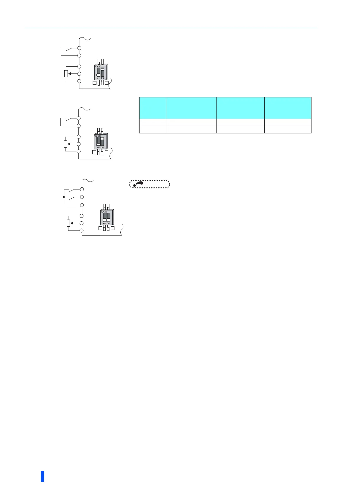
To run with an analog input voltage
• Concerning the frequency setting signal, input 0 to 5 VDC (or 0 to 10 VDC) to
terminals 2 and 5. The 5 V (10 V) input is the maximum output frequency.
• The power supply 5 V (10 V) can be input by either using the internal power
supply or preparing an external power supply. The internal power source is 5
VDC output between terminals 10 and 5, and 10 VDC output between
terminals 10E and 5.
• To supply the 10 VDC input to terminal 2, set "0, 2, 4, 10, 12, or 14" in Pr.73.
(The initial value is 0 to 5 V.)
• Setting "1 (0 to 5 VDC)" or "2 (0 to 10 VDC)" in Pr.267 and turning the voltage/
current input switches OFF sets the terminal 4 to the voltage input
specification. Turning ON the AU signal activates terminal 4 input.
NOTE
• The wiring length of the terminal 10, 2, 5 should be 30 m at maximum.
STF
Inverter
Forward
rotation
Frequency
setting
0 to 5 VDC
SD
10
2
5
Connection diagram using
terminal 2 (0 to 5 VDC)
Voltage/current
input switch
2
4
STF
Inverter
Forward
rotation
Frequency
setting
0 to 10 VDC
SD
10E
2
5
Connection diagram
using terminal 2 (0 to 10 VDC)
Voltage/current
input switch
2
4
STF
Inverter
Forward
rotation
SD
AU
Connection diagram
using terminal 4 (0 to 5 VDC)
Terminal 4
input selection
Frequency
setting
0 to 5 VDC
10
4
5
Voltage/current
input switch
2
4
Terminal
Inverter internal
power source
voltage
Frequency
setting
resolution
Pr.73
(terminal 2
input voltage)
10 5 VDC 0.030 Hz/60 Hz 0 to 5 VDC input
10E 10 VDC 0.015 Hz/60 Hz 0 to 10 VDC input

 Loading...


