(T) Multi-Function Input Terminal Parameters
PARAMETERS
407
5
GROUP
T
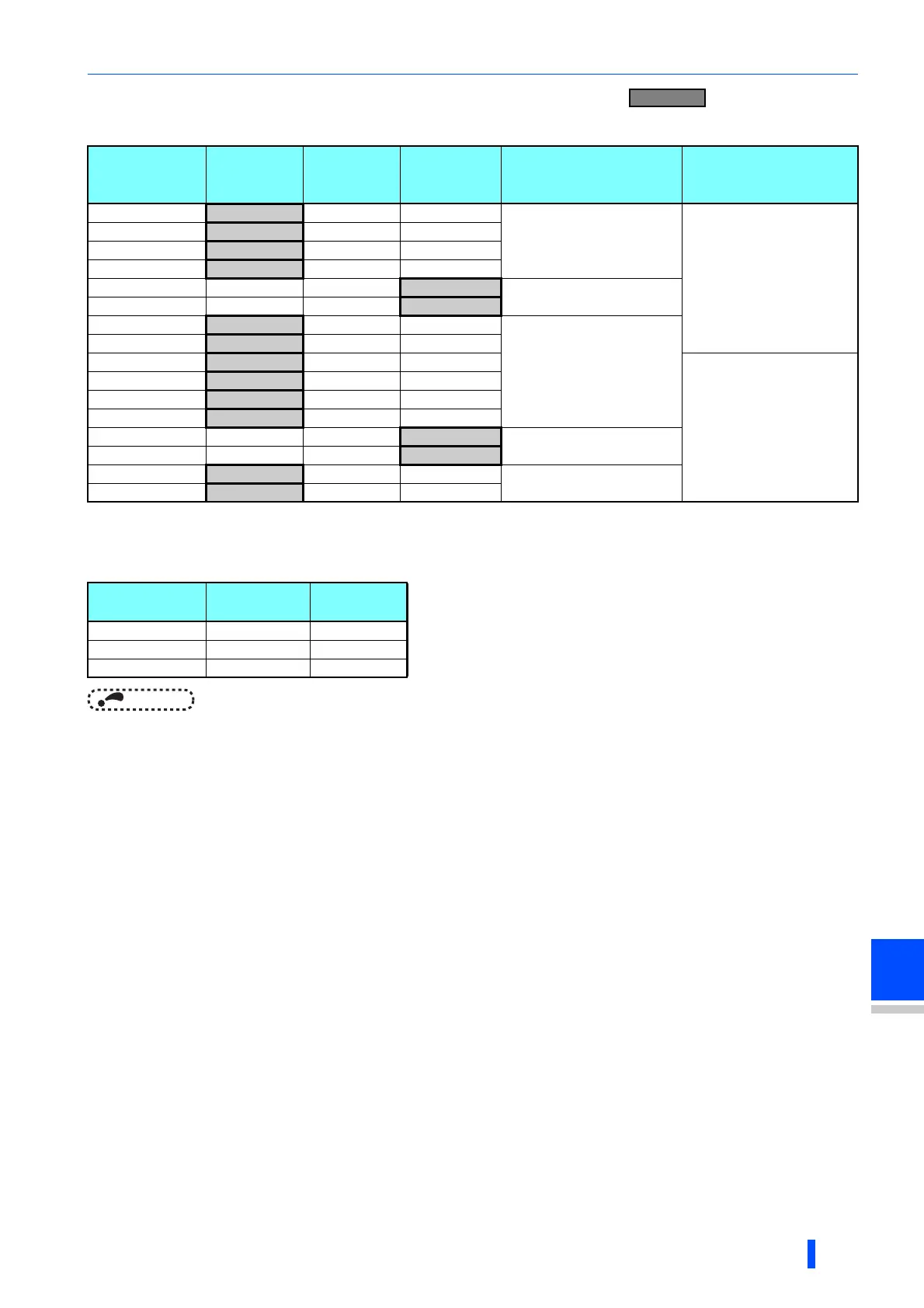
• Set the Pr.73 and voltage/current input switch settings according to the table below. ( indicates the main
speed setting.)
• Turning the Terminal 4 input selection(AU) signal ON sets terminal 4 to the main speed. With this setting, the main speed
setting terminal is invalidated.
• Set the Pr.267 and voltage/current input switch setting according to the table below.
NOTE
• To enable the terminal 4, turn the AU signal ON.
• Set the parameters and the switch settings so that they agree. Incorrect setting may cause a fault, failure or malfunction.
• Terminal 1 (frequency setting auxiliary input) is added to the terminal 2 or 4 main speed setting signal.
• When the override setting is selected, terminal 1 or 4 is set to the main speed setting, and terminal 2 is set to the override
signal (0 to 5 V or 0 to 10 V, and 50% to 150%). (If the main speed of terminal 1 or 4 is not input, the compensation by
terminal 2 is disabled.)
•Use Pr.125 (Pr.126) (frequency setting gain) to change the maximum output frequency at the input of the maximum output
frequency command voltage (current). At this time, the command voltage (current) need not be input.
The acceleration/deceleration time inclines up/down to the acceleration/deceleration reference frequency, so it is not affected
by change of Pr.73.
• When Pr.858 Terminal 4 function assignment and Pr.868 Terminal 1 function assignment = "4", the terminal 1 and
terminal 4 values are set to the stall prevention operation level.
• After the voltage/current input signal is switched with Pr.73, Pr.267, and voltage/current input switches, be sure to let
calibration performed.
• When Pr.561 PTC thermistor protection level "9999", terminal 2 does not function as an analog frequency command.
Pr.73 setting
Terminal 2
input
Switch 1
Terminal 1
input
Compensation input
terminal compensation
method
Polarity reversible
0 0 to 10 V OFF 0 to ±10 V
Terminal 1
Addition compensation
Not applied
(state in which a negative
polarity frequency command
signal is not accepted)
1 (initial value)
0 to 5 V OFF 0 to ±10 V
2
0 to 10 V OFF 0 to ±5 V
3
0 to 5 V OFF 0 to ±5 V
4 0 to 10 V OFF
0 to ±10 V
Terminal 2
Override
5 0 to 5 V OFF
0 to ±5 V
6
0 to 20 mA ON 0 to ±10 V
Terminal 1
Addition compensation
7
0 to 20 mA ON 0 to ±5 V
10
0 to 10 V OFF 0 to ±10 V
Applied
11
0 to 5 V OFF 0 to ±10 V
12
0 to 10 V OFF 0 to ±5 V
13
0 to 5 V OFF 0 to ±5 V
14 0 to 10 V OFF
0 to ±10 V
Terminal 2
Override
15 0 to 5 V OFF
0 to ±5 V
16
0 to 20 mA ON 0 to ±10 V
Terminal 1
Addition compensation
17
0 to 20 mA ON 0 to ±5 V
Pr.267 setting
Terminal 4
input
Switch 2
0 (initial value) 4 to 20 mA ON
1 0 to 5 V OFF
2 0 to 10 V OFF

 Loading...


