(G) Control parameters
PARAMETERS
619
5
GROUP
G
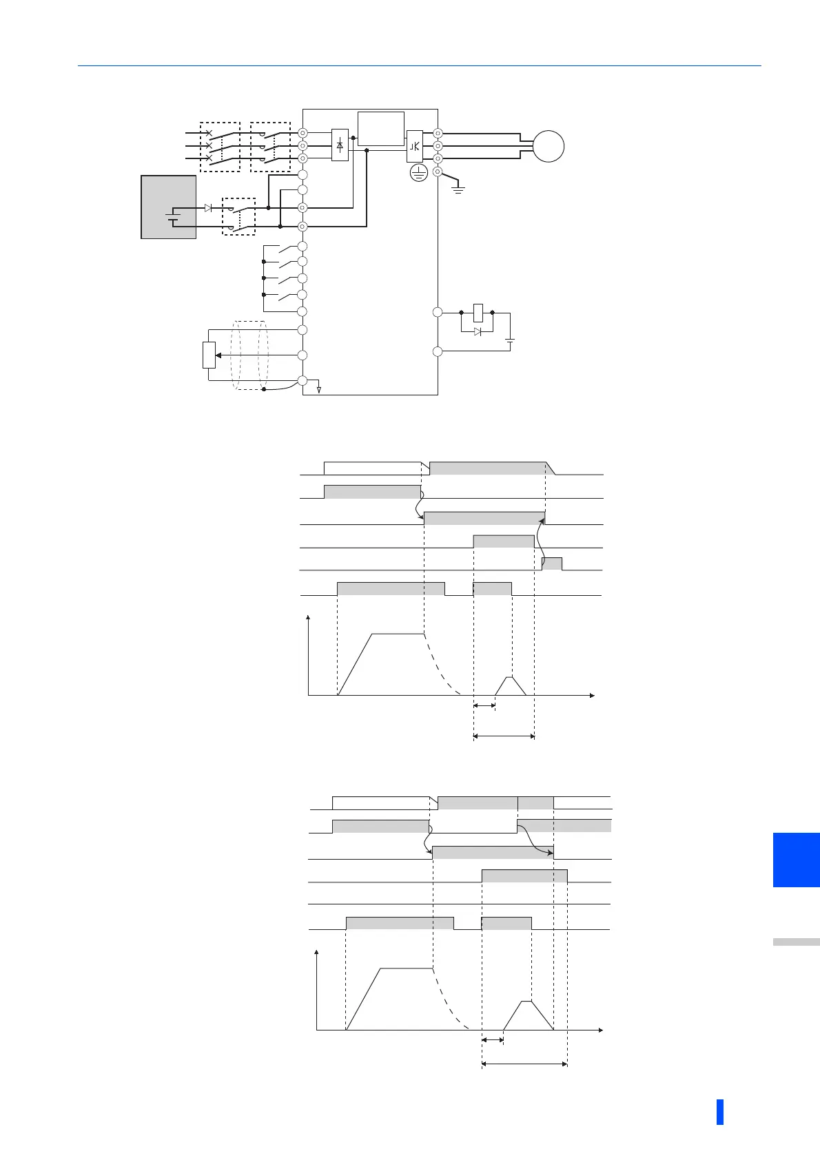
• Following is the connection diagram of switching to DC power supply using the power failure detection of the inverter.
Assign the function by setting Pr.178 to Pr.189 (input terminal function selection).
Assign the function by setting Pr.190 to Pr.196 (output terminal function selection).
• Operation example at the time of power failure occurrence 1
• Operation example at the time of power failure occurrence 2 (when the AC power supply is restored)
DC power
MCCB MC
R/L1
S/L2
T/L3
U
V
W
P/+
N/-
SE
Y85
IM
STF
STR
X70
X71
SD
R1/L11
S1/L21
Earth
(Ground)
10
2
2
3
1
5
(+)
(-)
∗1
MC1
MC1
Three-phase AC
power supply
DC feeding permission signal
DC feeding cancel signal
Contact input common
Reverse rotation start
Forward rotation start
∗1
∗2
Inverter
Inrush
current
limit circuit
Frequency command
Frequency setting
potentiometer
1/2W1kΩ
24VDC
DC feeding signal
Time
ON
ON
Back up operation
Motor
coasting
Approx.
200ms
STF(STR)
DC power supplyAC power supply
Control power
supply
ON
C power supply
ON
Y85(MC)
ON
X70
ON
X71
Output
frequency
(Hz)
Time
ON
ON
Back up operation
Motor
coasting
Turns off after stop
while running
Approx.200ms
STF(STR)
DCAC AC
Control power supply
ON
Power restoration
AC power supply
ON
Y85(MC)
ON
OFF
X70
X71
Output
frequency
(Hz)

 Loading...


