Causes and corrective actions
PROTECTIVE FUNCTIONS
659
6 5
Operation panel
indication
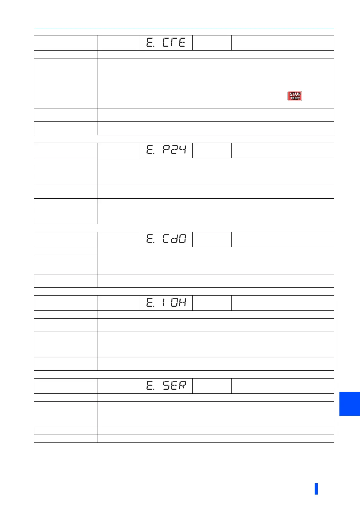
E.CTE FR-PU07 E.CTE
Name
Operation panel power supply short circuit/RS-485 terminals power supply short circuit
Description
• When the power supply for the operation panel (PU connector) is shorted, the power output is shutoff and
the inverter trips. The use of the operation panel (parameter unit) and the RS-485 communication via the PU
connector are disabled. To reset, enter the RES signal from the terminal, reset via communication through
the RS-485 terminals, or switch power OFF then ON again.
• When the power supply for the RS-485 terminals are short circuited, this function shuts off the power output.
At this time, communication from the RS-485 terminals cannot be made. To reset, use of the
operation panel, enter the RES signal, or switch power OFF then ON again.
Check point
• Check that the PU connector cable is not shorted.
• Check that the RS-485 terminals are connected correctly.
Corrective action
• Check PU and the cable.
• Check the connection of the RS-485 terminals.
Operation panel
indication
E.P24 FR-PU07 E.P24
Name
24 VDC power fault
Description
When the 24 VDC power output from the PC terminal is shorted, this function shuts off the power output.
At this time, all external contact inputs switch OFF. The inverter cannot be reset by entering the RES signal.
To reset it, use the operation panel, or switch power OFF, then ON again.
Check point
• Check for a short circuit in the PC terminal output.
• Check that the 24 V external power supply voltage is correct.
Corrective action
• Repair the short-circuited portion.
• Supply the power at 24 V. (If the power at insufficient voltage is supplied to the 24V input circuit for a long
time, the inverter internal circuit may heat up. Input power at correct voltage although it will not damage the
inverter.)
Operation panel
indication
E.CDO FR-PU07 OC detect level
Name
Abnormal output current detection
Description
The inverter trips if the output current exceeds the Pr.150 Output current detection level setting.
This functions is available when Pr.167 Output current detection operation selection is set to "1". When
the initial value (Pr.167 = "0") is set, this protective function is not available.
Check point
Check the settings of Pr.150, Pr.151 Output current detection signal delay time, Pr.166 Output current
detection signal retention time, and Pr.167. (Refer to page 395.)
Operation panel
indication
E.IOH FR-PU07 Inrush overheat
Name
Inrush current limit circuit fault (Standard models and IP55 compatible models only)
Description
The inverter trips when the resistor of the inrush current limit circuit is overheated. The inrush current limit
circuit failure
Check point
• Check that frequent power ON/OFF is not repeated.
• Check if the input side fuse (5A) in the power supply circuit of the inrush current limit circuit contactor (FR-
A840-03250(110K) or higher) is blown.
• Check that the power supply circuit of inrush current limit circuit contactor is not damaged.
Corrective action
Configure a circuit where frequent power ON/OFF is not repeated.
If the situation does not improve after taking the above measure, please contact your sales representative.
Operation panel
indication
E.SER FR-PU07 VFD Comm error
Name
Communication fault (inverter)
Description
The inverter trips when communication error occurs consecutively for the permissible number of retries or
more when Pr.335 RS-485 communication retry count "9999" during RS-485 communication from the
RS-485 terminals. The inverter also trips if communication is broken for the period of time set in Pr.336 RS-
485 communication check time interval.
Check point
Check the RS-485 terminal wiring.
Corrective action
Perform wiring of the RS-485 terminals properly.

 Loading...


