Raisecom
ISCOM2600G-HI (A) Series Configuration Guide
Raisecom Proprietary and Confidential
Copyright © Raisecom Technology Co., Ltd.
Raisecom#show vlan-mapping both interface
interface-type interface-number
Show configurations of
VLAN mapping.
Raisecom#show vlan-mapping interface
interface-type interface-number
both
translate
Show configurations of
N:1 VLAN mapping on
the interface.
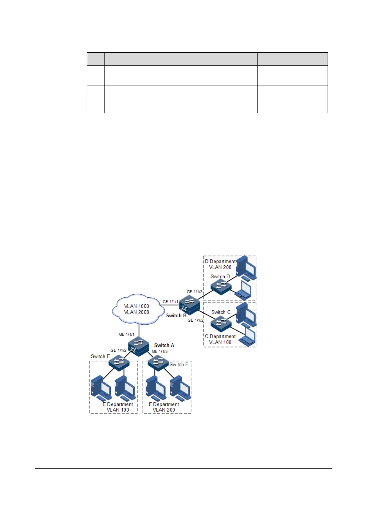
2.5.6 Example for configuring VLAN mapping
Scenario
As shown in Figure 2-10, GE 1/1/2 and GE 1/1/3 on Switch A are connected to Department E
using VLAN 100 and Department F using VLAN 200; GE 1/1/2 and GE 1/1/3 on Switch A
are connected to Department C using VLAN 100 and Department D using VLAN 200. The
carrier's network uses VLAN 1000 to transmit services between Department E and
Department C and uses VLAN 2008 to transmit services between Department F and
Department D.
Configure 1:1 VLAN mapping between Switch A and Switch B to implement normal
communication inside each department.
Figure 2-10 VLAN mapping networking
Configuration steps
Configure Switch A and Switch B.
Configuration steps for Switch A and Switch B are the same. Take Switch A for example.
 Loading...


