Raisecom
ISCOM2600G-HI (A) Series Configuration Guide
Raisecom Proprietary and Confidential
Copyright © Raisecom Technology Co., Ltd.
11.3.6 Example for configuring link-state tracking
Networking requirements
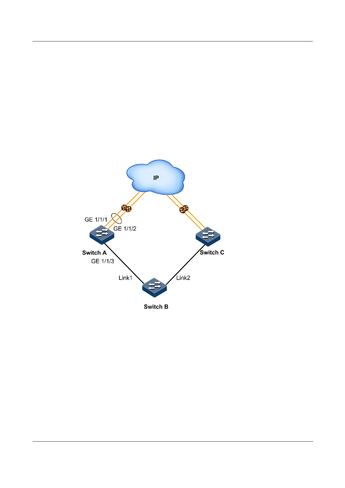
As shown in Figure 11-6, to improve network reliability, Link 1 and Link 2 of Switch B are
connected to Switch A and Switch C respectively. Link 1 is the active link and Link 2 is the
standby link. Link 2 will not be used to forward data until Link 1 is faulty.
Switch A and Switch C are connected to the uplink network in link aggregation mode. When
all uplink interfaces on Switch A and Switch C fails, Switch B needs to sense the fault in time
and switches traffic to the standby link. Therefore, you should deploy link-state tracking on
Switch A and Switch C.
Figure 11-6 Link-state tracking networking
Configuration steps
Step 1 Configure link-state tracking on Switch A.
Create a LAG. Add uplink interfaces GE 1/1/1 and GE 1/1/2 to the LAG.
Raisecom#config
Raisecom(config)#interface gigaethernet 1/1/1
Raisecom(config-gigaethernet1/1/1)#port-channel 1
Raisecom(config-gigaethernet1/1/1)#exit
Raisecom(config)#interface gigaethernet 1/1/2
Raisecom(config-gigaethernet1/1/2)#port-channel 1
Raisecom(config-gigaethernet1/1/2)#exit
 Loading...


