Raisecom
ISCOM2600G-HI (A) Series Configuration Guide
Raisecom Proprietary and Confidential
Copyright © Raisecom Technology Co., Ltd.
12.1.9 Checking configurations
Use the following commands to check configuration results.
Raisecom#show
snmp access
Show SNMP access group configurations.
Raisecom#show
snmp community
Show SNMP community configurations.
Raisecom#show
snmp config
Show SNMP basic configurations, including the local
SNMP engine ID, logo and contact method of the
administrator, physical location of the device, and Trap
status.
Show the mapping between SNMP users and the access
group.
Show Trap target host information.
Raisecom#show
snmp statistics
Show SNMP user information.
Show SNMP view information.
Raisecom#show
snmp server-auth
Show SNMP server authentication configurations.
12.1.10 Example for configuring SNMPv1/SNMPv2c and Trap
Networking requirements
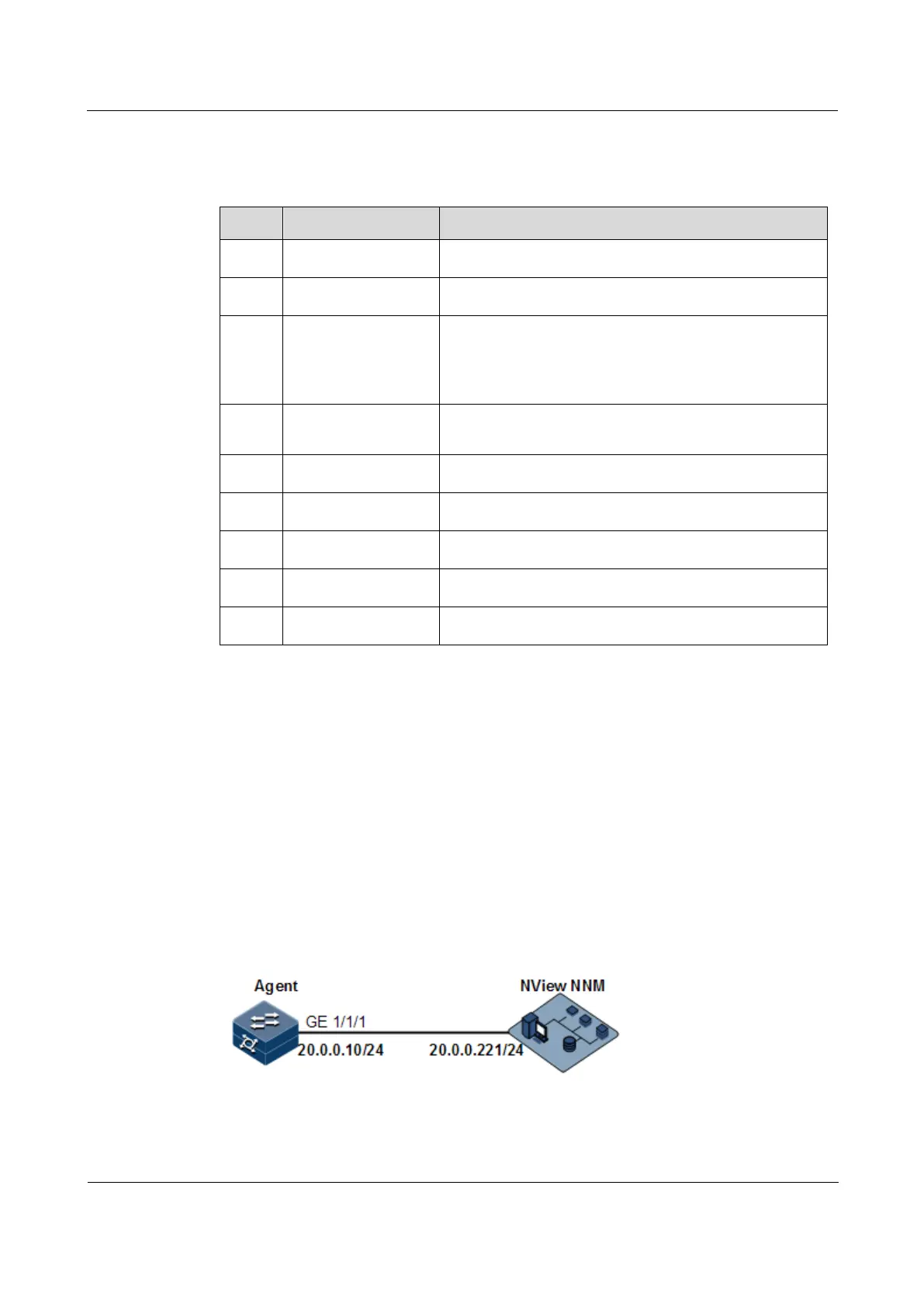
As shown in Figure 12-3, the route between the NView NNM system and the ISCOM2600G-
HI series switch is available. The NView NNM system can check the MIB under view
corresponding to the remote Switch by SNMPv1/SNMPv2c, and the ISCOM2600G-HI series
switch can send Trap automatically to the NView NNM system in emergency.
By default, there is VLAN 1 on the ISCOM2600G-HI series switch and all physical interfaces
belong to VLAN 1.
Figure 12-3 SNMPv1/SNMPv2c networking
 Loading...


