Raisecom
ISCOM2600G-HI (A) Series Configuration Guide
Raisecom Proprietary and Confidential
Copyright © Raisecom Technology Co., Ltd.
Raisecom#show mac-vlan aging-
time
Show the aging time of MAC VLANs.
Raisecom#show switchport
interface-type interface-number
Show VLAN configurations on the
interface.
Raisecom#show protocol-vlan all
Show configurations of all protocol
VLANs.
Raisecom#show protocol-vlan
interface
interface-type
interface-number
Show configurations of the protocol
VLAN on the interface.
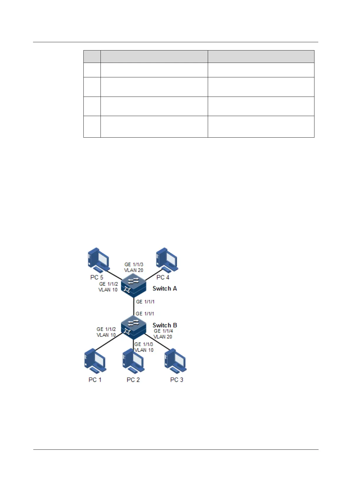
2.2.12 Example for configuring VLAN
Networking requirements
As shown in Figure 2-4, PC 1, PC 2, and PC 5 belong to VLAN 10, PC 3 and PC 4 belong to
VLAN 20; Switch A and Switch B are connected by the Trunk interface; PC 3 and PC 4
cannot communicate because VLAN 20 is not allowed to pass in the link; PC 1 and PC 2
under the same Switch B are enabled with interface protection function so that they cannot
communicate with each other, but can respectively communicate with PC 5.
Figure 2-4 VLAN and interface protection networking
Configuration steps
Step 1 Create VLAN 10 and VLAN 20 on the two switches respectively, and activate them.
Configure Switch A.
 Loading...


