RM0402 Rev 6 1117/1163
RM0402 USB on-the-go full-speed (OTG_FS)
1122
29.16.7 OTG programming model
The OTG_FS controller is an OTG device supporting HNP and SRP. When the core is
connected to an “A” plug, it is referred to as an A-device. When the core is connected to a
“B” plug it is referred to as a B-device. In host mode, the OTG_FS controller turns off V
BUS
to conserve power. SRP is a method by which the B-device signals the A-device to turn on
V
BUS
power. A device must perform both data-line pulsing and V
BUS
pulsing, but a host can
detect either data-line pulsing or V
BUS
pulsing for SRP. HNP is a method by which the B-
device negotiates and switches to host role. In Negotiated mode after HNP, the B-device
suspends the bus and reverts to the device role.
A-device session request protocol
The application must set the SRP-capable bit in the core USB configuration register. This
enables the OTG_FS controller to detect SRP as an A-device.
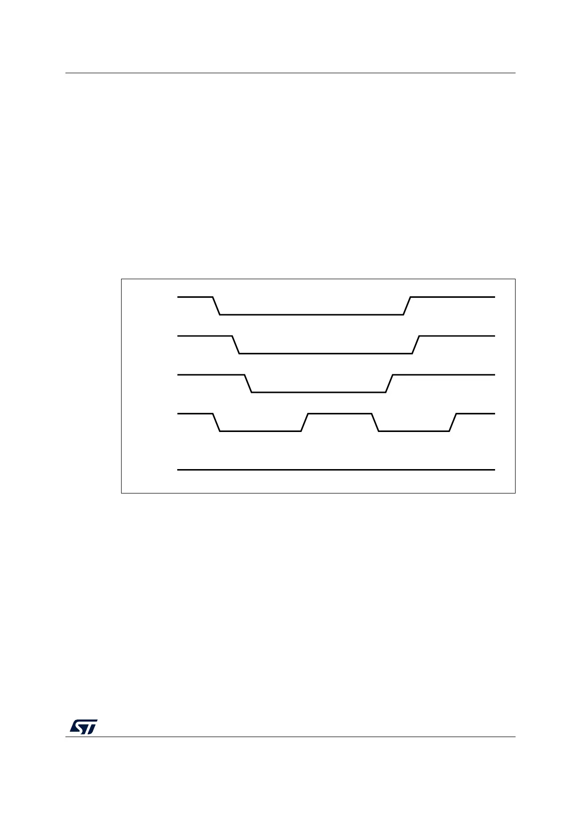
Figure 355. A-device SRP
1. DRV_VBUS = V
BUS
drive signal to the PHY
VBUS_VALID = V
BUS
valid signal from PHY
A_VALID = A-peripheral V
BUS
level signal to PHY
D+ = Data plus line
D- = Data minus line
The following points refer and describe the signal numeration shown in the Figure 355:
1. To save power, the application suspends and turns off port power when the bus is idle
by writing the port suspend and port power bits in the host port control and status
register.
2. PHY indicates port power off by deasserting the VBUS_VALID signal.
3. The device must detect SE0 for at least 2 ms to start SRP when V
BUS
power is off.
4. To initiate SRP, the device turns on its data line pull-up resistor for 5 to 10 ms. The
OTG_FS controller detects data-line pulsing.
5. The device drives V
BUS
above the A-device session valid (2.0 V minimum) for V
BUS
pulsing.
The OTG_FS controller interrupts the application on detecting SRP. The session
ai15681c
DRV_VBUS
VBUS_VALID
A_VALID
D+
D-
Suspend
V
BUS
pulsing
Data line pulsing
Connect
1
6
2
5
3
47
Low