Inter-integrated circuit (I
2
C) interface RM0402
748/1163 RM0402 Rev 6
24.6.3 I
2
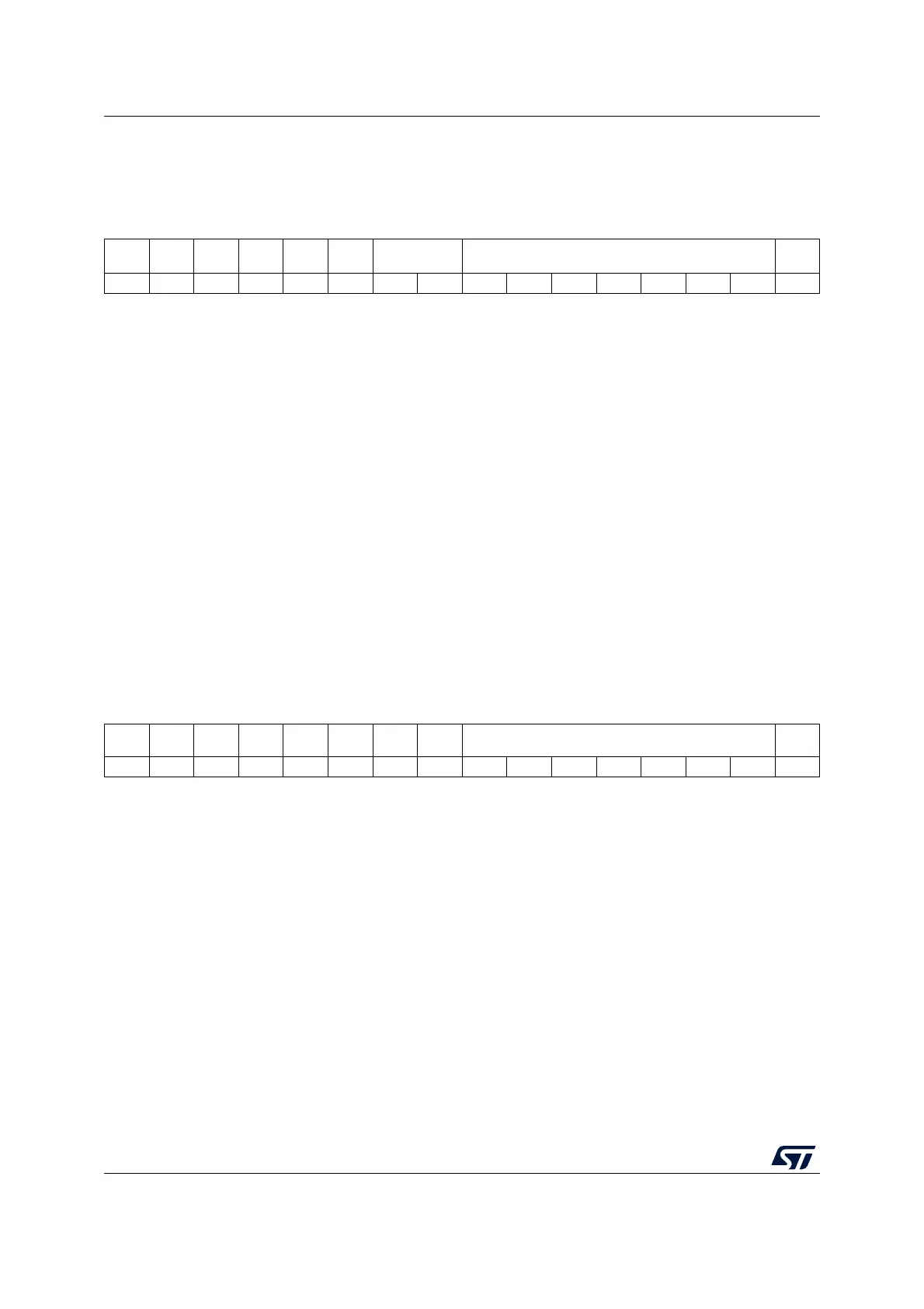
C own address register 1 (I2C_OAR1)
Address offset: 0x08
Reset value: 0x0000
24.6.4 I
2
C own address register 2 (I2C_OAR2)
Address offset: 0x0C
Reset value: 0x0000
15 14 13 12 11 10 9 8 7 6 5 4 3 2 1 0
ADD
MODE
Res. Res. Res. Res. Res. ADD[9:8] ADD[7:1] ADD0
rw rw rw rw rw rw rw rw rw rw rw
Bit 15 ADDMODE Addressing mode (slave mode)
0: 7-bit slave address (10-bit address not acknowledged)
1: 10-bit slave address (7-bit address not acknowledged)
Bit 14 Should always be kept at 1 by software.
Bits 13:10 Reserved, must be kept at reset value
Bits 9:8 ADD[9:8]: Interface address
7-bit addressing mode: don’t care
10-bit addressing mode: bits9:8 of address
Bits 7:1 ADD[7:1]: Interface address
bits 7:1 of address
Bit 0 ADD0: Interface address
7-bit addressing mode: don’t care
10-bit addressing mode: bit 0 of address
15 14 13 12 11 10 9 8 7 6 5 4 3 2 1 0
Res. Res. Res. Res. Res. Res. Res. Res. ADD2[7:1]
EN
DUAL
rw rw rw rw rw rw rw rw
Bits 15:8 Reserved, must be kept at reset value
Bits 7:1 ADD2[7:1]: Interface address
bits 7:1 of address in dual addressing mode
Bit 0 ENDUAL: Dual addressing mode enable
0: Only OAR1 is recognized in 7-bit addressing mode
1: Both OAR1 and OAR2 are recognized in 7-bit addressing mode