RM0402 Rev 6 651/1163
RM0402 Real-time clock (RTC)
655
22.6.18 RTC alarm A sub second register (RTC_ALRMASSR)
Address offset: 0x44
Backup domain reset value: 0x0000 0000
System reset: not affected
Bits 6:3 Reserved. Always read as 0.
Bit 2 TAMPIE: Tamper interrupt enable
0: Tamper interrupt disabled
1: Tamper interrupt enabled
Bit 1 TAMP1TRG: Active level for tamper 1
if TAMPFLT != 00:
0: TAMPER1 staying low triggers a tamper detection event.
1: TAMPER1 staying high triggers a tamper detection event.
if TAMPFLT = 00
:
0: TAMPER1 rising edge triggers a tamper detection event.
1: TAMPER1 falling edge triggers a tamper detection event.
Caution: When TAMPFLT = 0, TAMP1E must be reset when TAMP1TRG is changed to avoid
spuriously setting TAMP1F.
Bit 0 TAMP1E: Tamper 1 detection enable
0: Tamper 1 detection disabled
1: Tamper 1 detection enabled
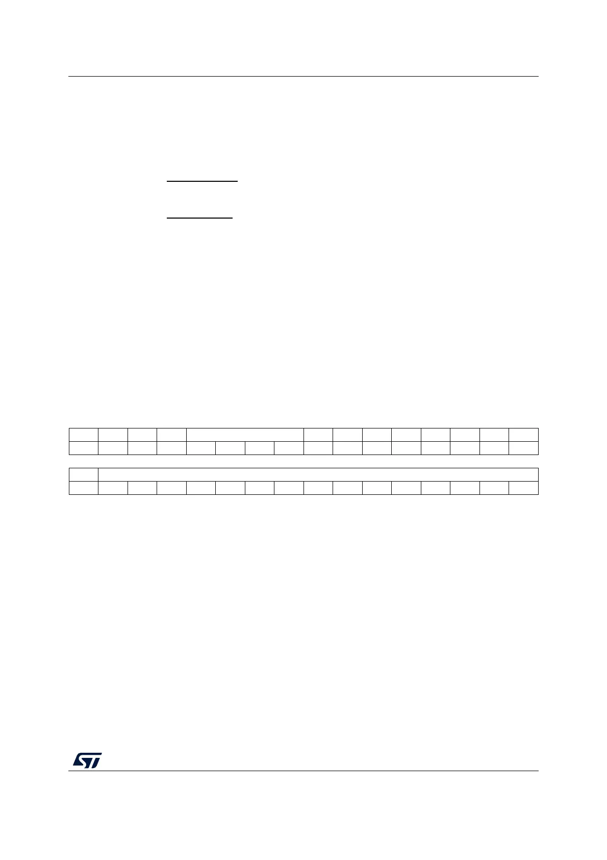
31 30 29 28 27 26 25 24 23 22 21 20 19 18 17 16
Res. Res. Res. Res. MASKSS[3:0] Res. Res. Res. Res. Res. Res. Res. Res.
rw rw rw rw
1514131211109876543210
Res. SS[14:0]
rw rw rw rw rw rw rw rw rw rw rw rw w rw rw
Bits 31:28 Reserved, must be kept at reset value
Bits 27:24 MASKSS[3:0]: Mask the most-significant bits starting at this bit
0: No comparison on sub seconds for Alarm A. The alarm is set when the seconds unit is
incremented (assuming that the rest of the fields match).
1: SS[14:1] are don’t care in Alarm A comparison. Only SS[0] is compared.
2: SS[14:2] are don’t care in Alarm A comparison. Only SS[1:0] are compared.
3: SS[14:3] are don’t care in Alarm A comparison. Only SS[2:0] are compared.
...
12: SS[14:12] are don’t care in Alarm A comparison. SS[11:0] are compared.
13: SS[14:13] are don’t care in Alarm A comparison. SS[12:0] are compared.
14: SS[14] is don’t care in Alarm A comparison. SS[13:0] are compared.
15: All 15 SS bits are compared and must match to activate alarm.
The overflow bits of the synchronous counter (bits 15) is never compared. This bit can be
different from 0 only after a shift operation.