RM0402 Rev 6 923/1163
RM0402 Controller area network (bxCAN)
966
28.3 bxCAN general description
In today CAN applications, the number of nodes in a network is increasing and often several
networks are linked together via gateways. Typically the number of messages in the system
(to be handled by each node) has significantly increased. In addition to the application
messages, Network Management and Diagnostic messages have been introduced.
• An enhanced filtering mechanism is required to handle each type of message.
Furthermore, application tasks require more CPU time, therefore real-time constraints
caused by message reception have to be reduced.
• A receive FIFO scheme allows the CPU to be dedicated to application tasks for a long
time period without losing messages.
The standard HLP (Higher Layer Protocol) based on standard CAN drivers requires an
efficient interface to the CAN controller.
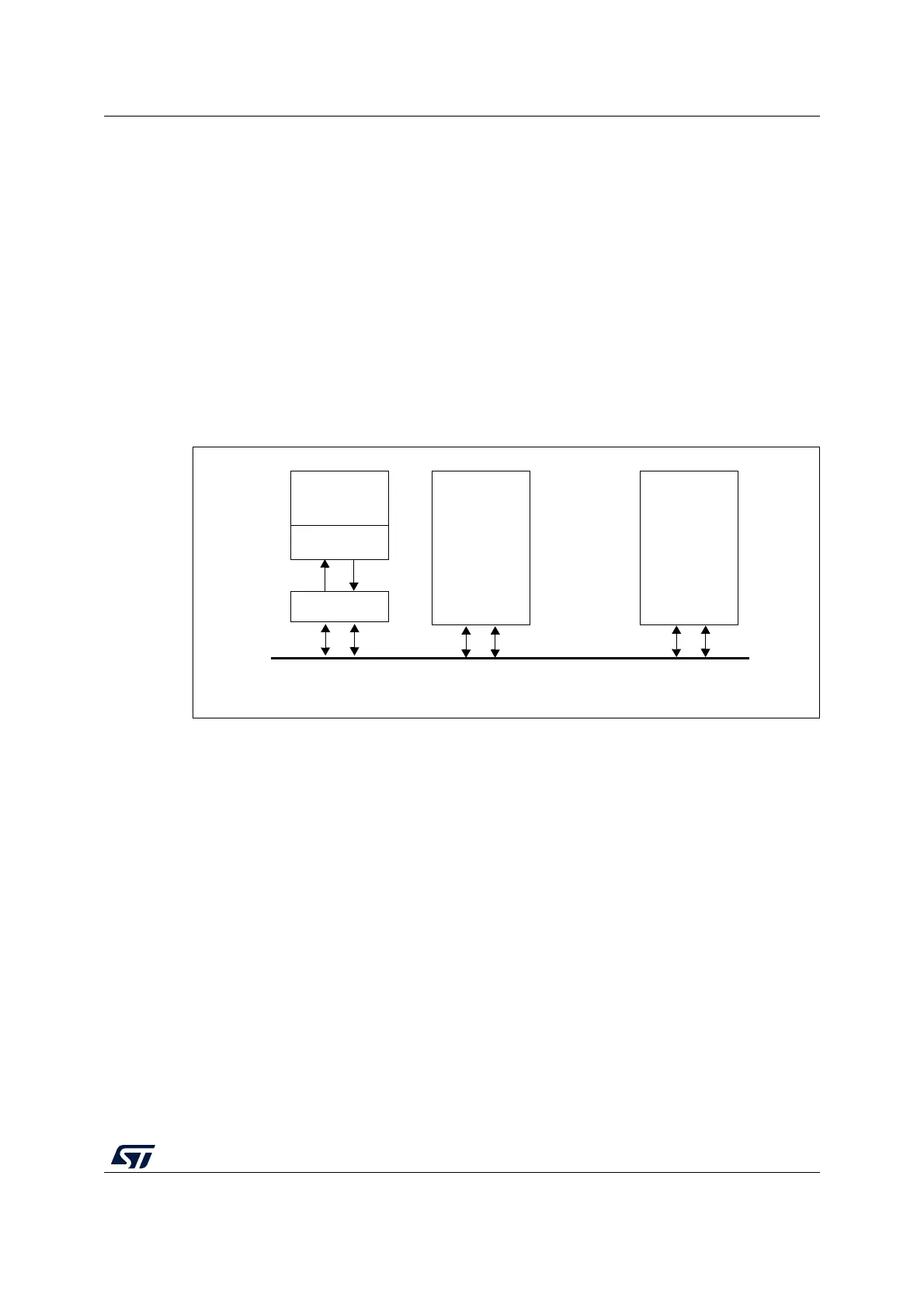
Figure 318. CAN network topology
28.3.1 CAN 2.0B active core
The bxCAN module handles the transmission and the reception of CAN messages fully
autonomously. Standard identifiers (11-bit) and extended identifiers (29-bit) are fully
supported by hardware.
28.3.2 Control, status and configuration registers
The application uses these registers to:
• Configure CAN parameters, e.g. baud rate
• Request transmissions
• Handle receptions
• Manage interrupts
• Get diagnostic information
28.3.3 Tx mailboxes
Three transmit mailboxes are provided to the software for setting up messages. The
transmission Scheduler decides which mailbox has to be transmitted first.
CAN node 1
CAN node 2
CAN node n
CAN
CAN
High Low
CAN
CAN
Rx
Tx
CAN
Transceiver
CAN
Controller
MCU
CAN Bus
Application
MS30392V1