RM0402 Rev 6 521/1163
RM0402 General-purpose timers (TIM2 to TIM5)
544
counters are aligned, Timer 1 must be configured in Master/Slave mode (slave with respect
to TI1, master with respect to Timer 2):
• Configure Timer 1 master mode to send its Enable as trigger output (MMS=001 in the
TIM1_CR2 register).
• Configure Timer 1 slave mode to get the input trigger from TI1 (TS=100 in the
TIM1_SMCR register).
• Configure Timer 1 in trigger mode (SMS=110 in the TIM1_SMCR register).
• Configure the Timer 1 in Master/Slave mode by writing MSM=1 (TIM1_SMCR register).
• Configure Timer 2 to get the input trigger from Timer 1 (TS=000 in the TIM2_SMCR
register).
• Configure Timer 2 in trigger mode (SMS=110 in the TIM2_SMCR register).
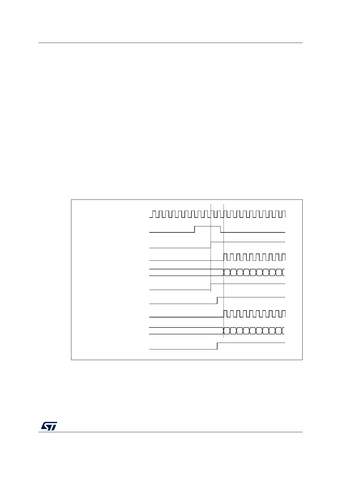
When a rising edge occurs on TI1 (Timer 1), both counters starts counting synchronously on
the internal clock and both TIF flags are set.
Note: In this example both timers are initialized before starting (by setting their respective UG
bits). Both counters starts from 0, but an offset can easily be inserted between them by
writing any of the counter registers (TIMx_CNT). One can see that the master/slave mode
insert a delay between CNT_EN and CK_PSC on timer 1.
Figure 170. Triggering timer 1 and 2 with timer 1 TI1 input
17.3.16 Debug mode
When the microcontroller enters debug mode (Cortex
®
-M4 with FPU core - halted), the
TIMx counter either continues to work normally or stops, depending on DBG_TIMx_STOP
configuration bit in DBGMCU module. For more details, refer to
Section 33.16.2: Debug
support for timers, watchdog, bxCAN and I
2
C.
MS37392V1
CK_INT
TIMER2-CNT
TIMER1-CEN=CNT_EN
TIMER2-TIF
01
TIMER1-CNT
02 03 04 05 06 07 08 0900
TIMER2-CEN=CNT_EN
TIMER1-TIF
TIMER1-CK_PSC
TIMER1-TI1
TIMER2-CK_PSC
01 02 03 04 05 06 07 08 0900