Digital filter for sigma delta modulators (DFSDM) RM0402
388/1163 RM0402 Rev 6
Note: The bits of DFSDM_FLTxICR are always read as ‘0’.
14.8.5 DFSDM filter x injected channel group selection register
(DFSDM_FLTxJCHGR)
Address offset: 0x110 + 0x80 * x, (x = 0 to 1)
Reset value: 0x0000 0001
Bits 31:28 Reserved, must be kept at reset value.
Bits 27:24 CLRSCDF[3:0]: Clear the short-circuit detector flag
CLRSCDF[y]=0: Writing ‘0’ has no effect
CLRSCDF[y]=1: Writing ‘1’ to position y clears the corresponding SCDF[y] bit in the
DFSDM_FLTxISR register
Note: CLRSCDF[3:0] is present only in DFSDM_FLT0ICR register (filter x=0)
Bits 23:20 Reserved, must be kept at reset value.
Bits 19:16 CLRCKABF[3:0]: Clear the clock absence flag
CLRCKABF[y]=0: Writing ‘0’ has no effect
CLRCKABF[y]=1: Writing ‘1’ to position y clears the corresponding CKABF[y] bit in the
DFSDM_FLTxISR register. When the transceiver is not yet synchronized, the clock absence flag is
set and cannot be cleared by CLRCKABF[y].
Note: CLRCKABF[3:0] is present only in DFSDM_FLT0ICR register (filter x=0)
Bits 15:4 Reserved, must be kept at reset value.
Bit 3 CLRROVRF: Clear the regular conversion overrun flag
0: Writing ‘0’ has no effect
1: Writing ‘1’ clears the ROVRF bit in the DFSDM_FLTxISR register
Bit 2 CLRJOVRF: Clear the injected conversion overrun flag
0: Writing ‘0’ has no effect
1: Writing ‘1’ clears the JOVRF bit in the DFSDM_FLTxISR register
Bits 1:0 Reserved, must be kept at reset value.
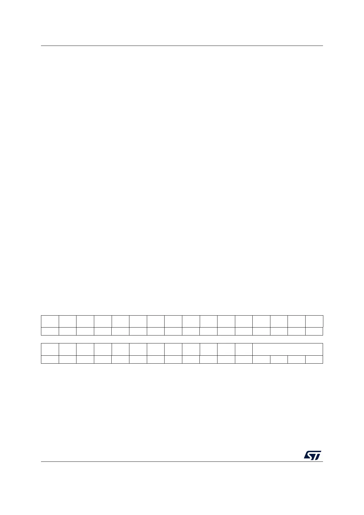
31 30 29 28 27 26 25 24 23 22 21 20 19 18 17 16
Res. Res. Res. Res. Res. Res. Res. Res. Res. Res. Res. Res. Res. Res. Res. Res.
1514131211109876543210
Res. Res. Res. Res. Res. Res. Res. Res. Res. Res. Res. Res. JCHG[3:0]
rw rw rw rw