RM0402 Rev 6 519/1163
RM0402 General-purpose timers (TIM2 to TIM5)
544
counts until we write ‘0 to the CEN bit in the TIM2_CR1 register. Both counter clock
frequencies are divided by 3 by the prescaler compared to CK_INT (f
CK_CNT
= f
CK_INT
/3).
• Configure Timer 1 master mode to send its Update Event (UEV) as trigger output
(MMS=010 in the TIM1_CR2 register).
• Configure the Timer 1 period (TIM1_ARR registers).
• Configure Timer 2 to get the input trigger from Timer 1 (TS=000 in the TIM2_SMCR
register).
• Configure Timer 2 in trigger mode (SMS=110 in TIM2_SMCR register).
• Start Timer 1 by writing ‘1 in the CEN bit (TIM1_CR1 register).
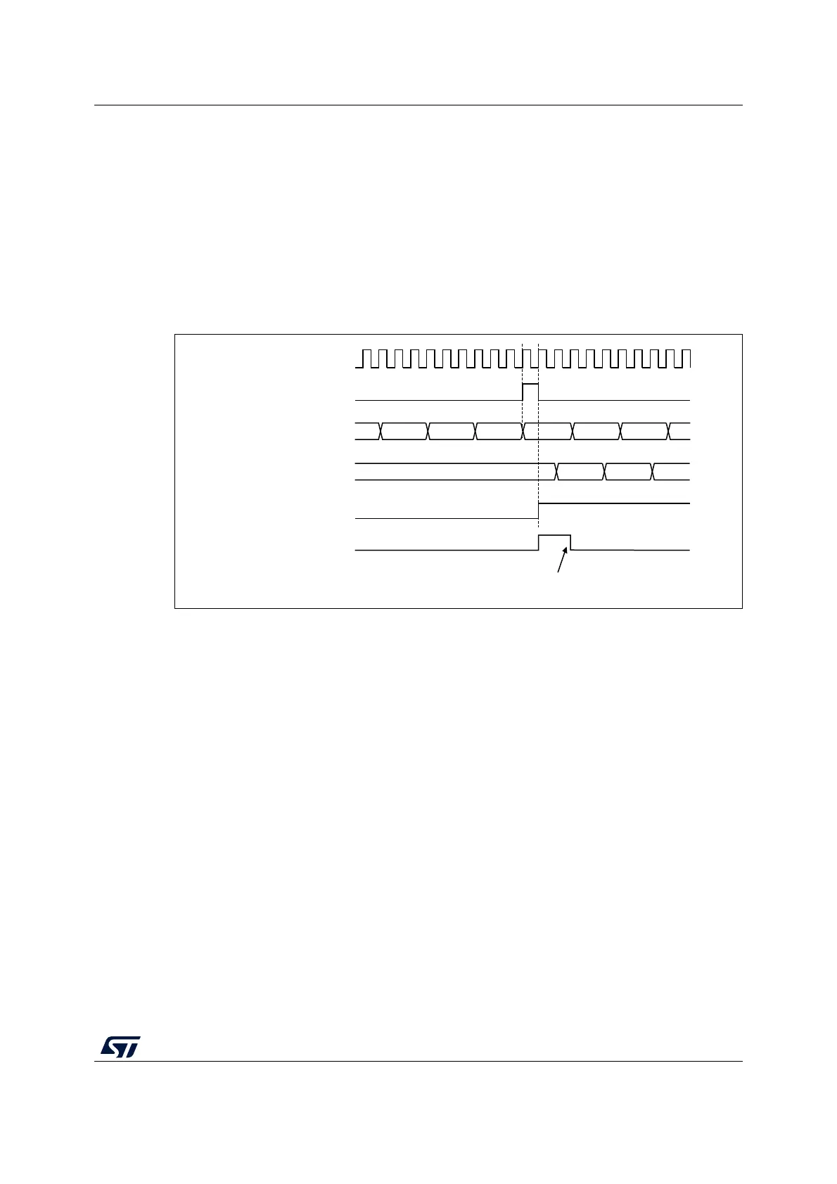
Figure 168. Triggering timer 2 with update of timer 1
As in the previous example, both counters can be initialized before starting counting.
Figure 169 shows the behavior with the same configuration as in Figure 166, but in trigger
mode instead of gated mode (SMS=110 in the TIM2_SMCR register).
MS37390V1
Write TIF = 0
CK_INT
TIMER2-CNT
FD
TIMER1-CNT
TIMER2-CEN=CNT_EN
TIMER2-TIF
FE FF 00 01 02
46 47 4845
TIMER1-UEV