RM0402 Rev 6 321/1163
RM0402 Analog-to-digital converter (ADC)
347
Note: Injected channels cannot be converted continuously. The only exception is when an injected
channel is configured to be converted automatically after regular channels in continuous
mode (using JAUTO bit), refer to
Auto-injection section).
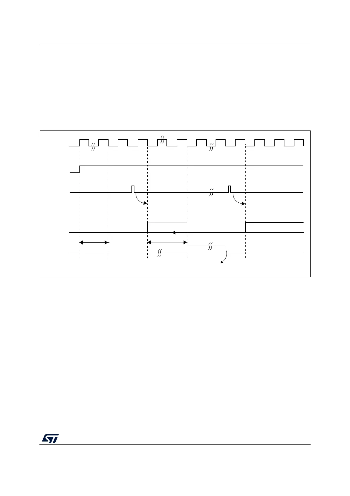
13.3.6 Timing diagram
As shown in Figure 60, the ADC needs a stabilization time of t
STAB
before it starts
converting accurately. After the start of the ADC conversion and after 15 clock cycles, the
EOC flag is set and the 16-bit ADC data register contains the result of the conversion.
Figure 60. Timing diagram
13.3.7 Analog watchdog
The AWD analog watchdog status bit is set if the analog voltage converted by the ADC is
below a lower threshold or above a higher threshold. These thresholds are programmed in
the 12 least significant bits of the ADC_HTR and ADC_LTR 16-bit registers. An interrupt can
be enabled by using the AWDIE bit in the ADC_CR1 register.
The threshold value is independent of the alignment selected by the ALIGN bit in the
ADC_CR2 register. The analog voltage is compared to the lower and higher thresholds
before alignment.
Table 75 shows how the ADC_CR1 register should be configured to enable the analog
watchdog on one or more channels.
ADC_CLK
EOC
Next ADC conversion
ADC conversion
Conversion time
t
STAB
ADC
Software clears the EOC bit
(total conv. time)
Start 1st conversion Start next conversion
ai16047b
ADON
SWSTART/
JSWSTART