Controller area network (bxCAN) RM0402
934/1163 RM0402 Rev 6
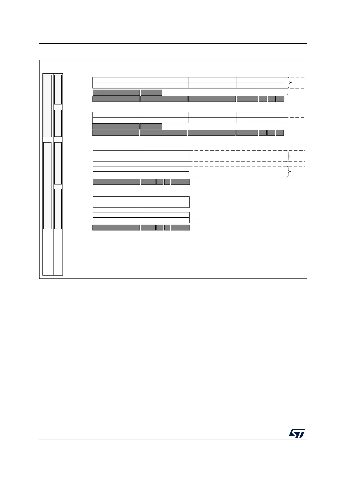
Figure 326. Filter bank scale configuration - register organization
Filter match index
Once a message has been received in the FIFO it is available to the application. Typically,
application data is copied into SRAM locations. To copy the data to the right location the
application has to identify the data by means of the identifier. To avoid this, and to ease the
access to the SRAM locations, the CAN controller provides a Filter Match Index.
This index is stored in the mailbox together with the message according to the filter priority
rules. Thus each received message has its associated filter match index.
The Filter Match index can be used in two ways:
• Compare the Filter Match index with a list of expected values.
• Use the Filter Match Index as an index on an array to access the data destination
location.
For non masked filters, the software no longer has to compare the identifier.
If the filter is masked the software reduces the comparison to the masked bits only.
MSv30398V4
One 32-Bit Filter - Identifier Mask
x = filter bank number
FSCx = 1FSCx = 0
1
These bits are located in the CAN_FS1R register
Filter Bank Scale
ID
Mask
ID
STID[10:3]
Mapping STD ID
ID
ID
ID
ID
ID
ID
ID
n
2
n
n
2
n
Config. Bits
1
ID=Identifier
FBMx = 1
FBMx = 0
FBMx = 0
FBMx = 1
Filter Bank Mode
Two 32-Bit Filters - Identifier List
Two 16-Bit Filters - Identifier Mask
Four 16-Bit Filters - Identifier List
Mapping
Mapping
CAN_FxR1[31:24]
CAN_FxR2[31:24] CAN_FxR2[23:16]
CAN_FxR1[23:16] CAN_FxR1[15:8]
CAN_FxR2[15:8]
CAN_FxR1[7:0]
CAN_FxR2[7:0]
CAN_FxR1[31:24]
CAN_FxR2[31:24] CAN_FxR2[23:16]
CAN_FxR1[23:16] CAN_FxR1[15:8]
CAN_FxR2[15:8]
CAN_FxR1[7:0]
CAN_FxR2[7:0]
CAN_FxR1[15:8]
CAN_FxR1[31:24]
CAN_FxR1[7:0]
CAN_FxR1[23:16]
CAN_FxR2[15:8]
CAN_FxR2[31:24]
CAN_FxR2[7:0]
CAN_FxR2[23:16]
CAN_FxR1[15:8]
CAN_FxR1[31:24]
CAN_FxR1[7:0]
CAN_FxR1[23:16]
CAN_FxR2[15:8]
CAN_FxR2[31:24]
CAN_FxR2[7:0]
CAN_FxR2[23:16]
These bits are located in the CAN_FM1R register
n+1
n+2
n+3
n+1
n+1
Filter
Num.
Mask
Mask
STID[2:0]
EXID[17:15]IDERTRSTID[2:0]STID[10:3]
EXID[17:15]
IDE
RTR
STID[2:0]
STID[10:3]
EXTID[28:21]
Mapping Ext ID
0
EXID[20:13]
EXID[12:5] EXID[4:0] IDE RTR
STID[10:3]
Mapping STD ID
STID[2:0]
EXTID[28:21]
Mapping Ext ID
0
EXID[20:13]
EXID[12:5] EXID[4:0] IDE RTR