USB on-the-go full-speed (OTG_FS) RM0402
1038/1163 RM0402 Rev 6
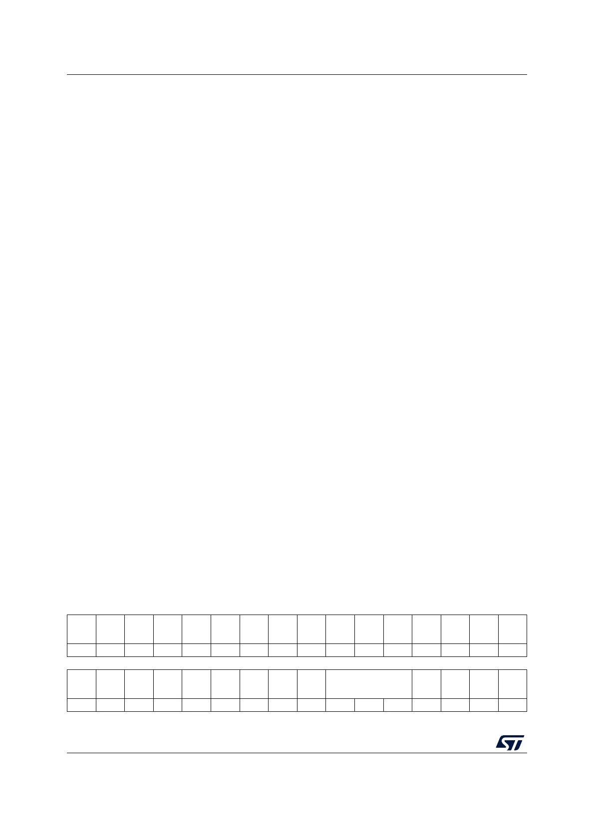
29.15.34 OTG device control register (OTG_DCTL)
Address offset: 0x804
Reset value: 0x0000 0002
Bits 31:16 Reserved, must be kept at reset value.
Bit 15 ERRATIM: Erratic error interrupt mask
1: Mask early suspend interrupt on erratic error
0: Early suspend interrupt is generated on erratic error
Bit 13 Reserved, must be kept at reset value.
Bits 12:11 PFIVL[1:0]: Periodic frame interval
Indicates the time within a frame at which the application must be notified using the end of
periodic frame interrupt. This can be used to determine if all the isochronous traffic for that
frame is complete.
00: 80% of the frame interval
01: 85% of the frame interval
10: 90% of the frame interval
11: 95% of the frame interval
Bits 10:4 DAD[6:0]: Device address
The application must program this field after every SetAddress control command.
Bit 3 Reserved, must be kept at reset value.
Bit 2 NZLSOHSK: Non-zero-length status OUT handshake
The application can use this field to select the handshake the core sends on receiving a
nonzero-length data packet during the OUT transaction of a control transfer’s status stage.
1:Send a STALL handshake on a nonzero-length status OUT transaction and do not send
the received OUT packet to the application.
0:Send the received OUT packet to the application (zero-length or nonzero-length) and send
a handshake based on the NAK and STALL bits for the endpoint in the device endpoint
control register.
Bits 1:0 DSPD[1:0]: Device speed
Indicates the speed at which the application requires the core to enumerate, or the
maximum speed the application can support. However, the actual bus speed is determined
only after the chirp sequence is completed, and is based on the speed of the USB host to
which the core is connected.
00: Reserved
01: Reserved
10: Reserved
11: Full speed (USB 1.1 transceiver clock is 48 MHz)
31 30 29 28 27 26 25 24 23 22 21 20 19 18 17 16
Res. Res. Res. Res. Res. Res. Res. Res. Res. Res. Res. Res. Res.
DS
BESL
RJCT
Res. Res.
rw
1514131211109876543210
Res. Res. Res. Res.
PO
PRG
DNE
CGO
NAK
SGO
NAK
CGI
NAK
SGI
NAK
TCTL[2:0]
GON
STS
GIN
STS
SDIS
RWU
SIG
rwwwwwrwrwrwr rrwrw