RM0402 Rev 6 979/1163
RM0402 USB on-the-go full-speed (OTG_FS)
1122
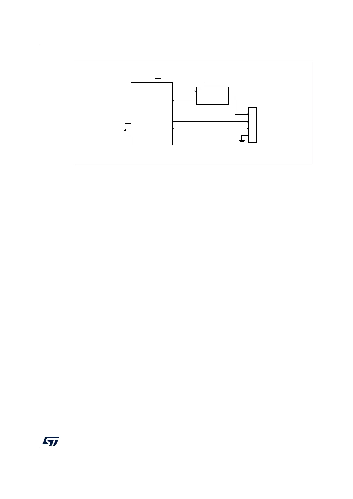
Figure 337. OTG_FS host-only connection
1. V
DD
range is between 2 V and 3.6 V.
29.7.1 SRP-capable host
SRP support is available through the SRP capable bit in the global USB configuration
register (SRPCAP bit in OTG_GUSBCFG). With the SRP feature enabled, the host can
save power by switching off the V
BUS
power while the USB session is suspended.
The SRP host mode program model is described in detail in the A-device session request
protocol) section.
29.7.2 USB host states
Host port power
On-chip 5 V V
BUS
generation is not supported. For this reason, a charge pump or, if 5 V are
available on the application board, a basic power switch, must be added externally to drive
the 5
V V
BUS
line. The external charge pump can be driven by any GPIO output or via an
I
2
C interface connected to an external PMIC (power management IC). When the application
decides to power on V
BUS
, it must also set the port power bit in the host port control and
status register (PPWR bit in OTG_HPRT).
V
BUS
valid
When HNP or SRP is enabled the VBUS sensing pin should be connected to V
BUS
. The
V
BUS
input ensures that valid V
BUS
levels are supplied by the charge pump during USB
operations. Any unforeseen V
BUS
voltage drop below the V
BUS
valid threshold (4.4 V) leads
to an OTG interrupt triggered by the session end detected bit (SEDET bit in
OTG_GOTGINT). The application is then required to remove the V
BUS
power and clear the
port power bit.
When HNP and SRP are both disabled, the VBUS sensing pin does not need to be
connected to V
BUS
.
The charge pump overcurrent flag can also be used to prevent electrical damage. Connect
the overcurrent flag output from the charge pump to any GPIO input and configure it to
generate a port interrupt on the active level. The overcurrent ISR must promptly disable the
V
BUS
generation and clear the port power bit.
MSv36915V2
STMPS2141STR
Current-limited
power distribution
switch
(2)
OSC_IN
OSC_OUT
GPIO
GPIO + IRQ
EN
Overcurrent
5 V
5 V Pwr
VBUS
DM
DP
V
SS
USB Std-A connector
V
DD