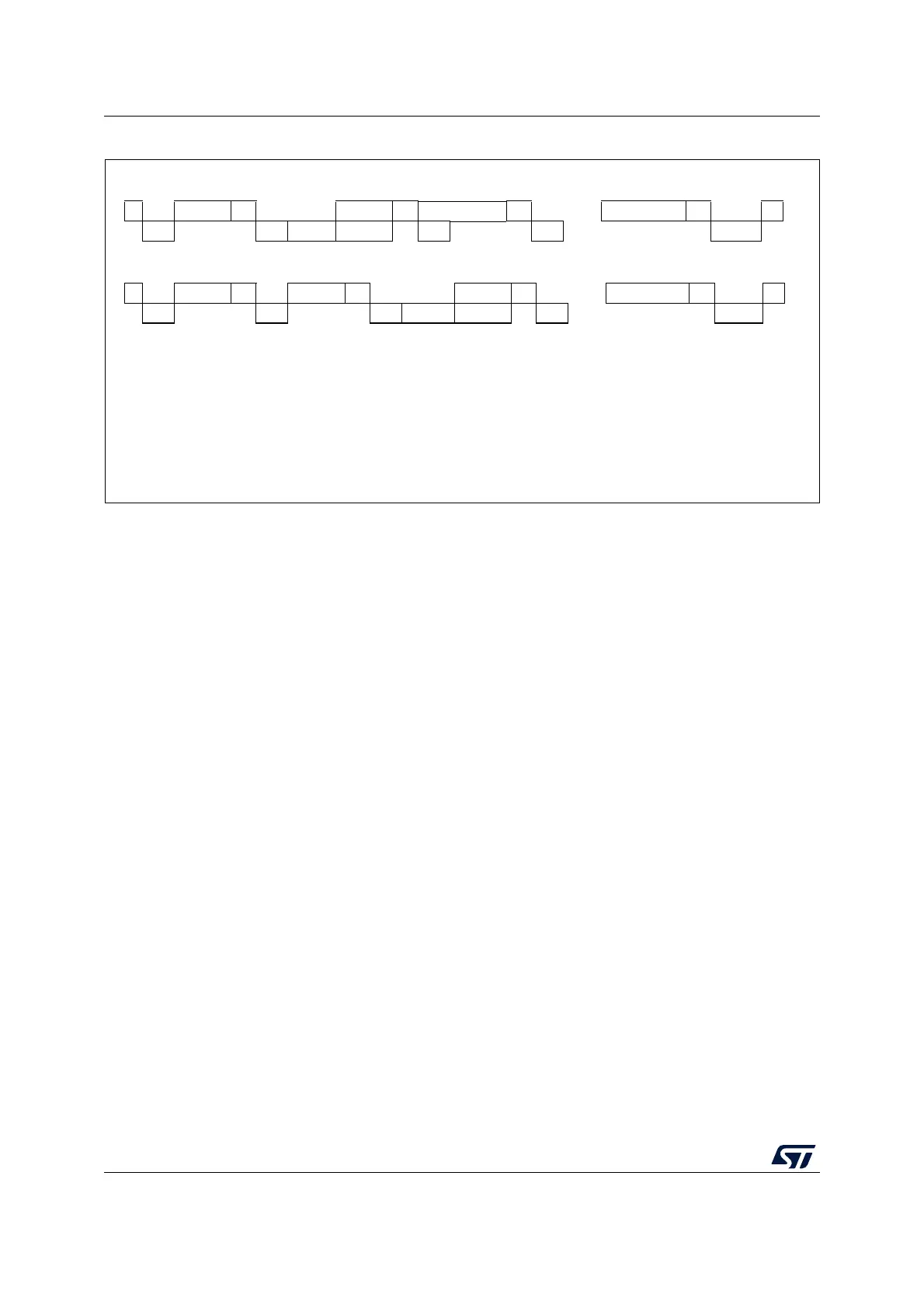
Figure 242. Transfer sequence diagram for master transmitter
1. The EV5, EV6, EV9, EV8_1 and EV8_2 events stretch SCL low until the end of the corresponding software sequence.
2. The EV8 event stretches SCL low if the software sequence is not complete before the end of the next byte transmission.
7-bit master transmitter
A
.....
.....
ai18210V2
S Address
A
Data1
Data2A
DataN
A
P
EV5
EV6
EV8_1
EV8
EV8 EV8
EV8_2
DataN
A
P
EV8_2
Data1 A
EV8 EV8EV8_1EV6
S
EV5
Header A Address A
EV9
10-bit master transmitter
Legend: S = Start, SR = Repeated start, P = stop, A = Acknowledge
EVx = Event (with interrupt if ITEVFEN = 1)
EV5: SB=1, cleared by reading SR1 register followed by writing DR register with address.
EV6: ADDR=1, cleared by reading SR1 register followed by reading SR2.
EV8_1: TxE=1, shift register empty, data register empty, write Data1 in DR.
EV8: TxE=1, shift register not empty, data register empty, cleared by writing DR register.
EV_2: TxE=1, BTF=1, Program stop request, TxE and BTF are cleared by hardware by the stop condition.
EV9: ADD10=1, cleared by reading SR1 register followed by writing DR register.