RM0402 Rev 6 763/1163
RM0402 Universal synchronous receiver transmitter (USART) /universal asynchronous receiver
810
25.4.1 USART character description
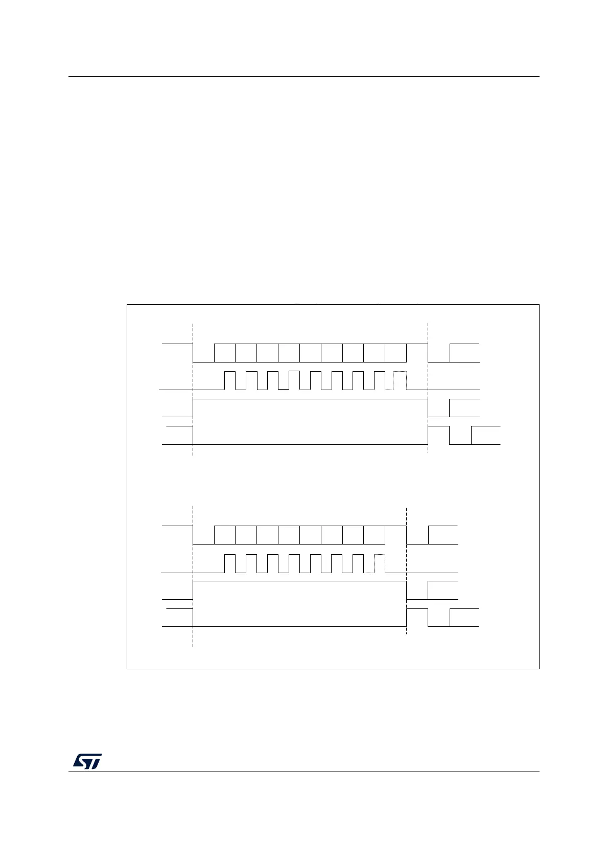
Word length may be selected as being either 8 or 9 bits by programming the M bit in the
USART_CR1 register (see
Figure 246).
The TX pin is in low state during the start bit. It is in high state during the stop bit.
An Idle character is interpreted as an entire frame of “1”s followed by the start bit of the
next frame that contains data (The number of “1” ‘s will include the number of stop bits).
A Break character is interpreted on receiving “0”s for a frame period. At the end of the
break frame the transmitter inserts either 1 or 2 stop bits (logic “1” bit) to acknowledge the
start bit.
Transmission and reception are driven by a common baud rate generator, the clock for each
is generated when the enable bit is set respectively for the transmitter and receiver.
The details of each block is given below.
Figure 246. Word length programming
MS37358V1
Bit0 Bit1 Bit2 Bit3 Bit4 Bit5 Bit6 Bit7 Bit8
Start
bit
Stop
bit
Next
Start
bit
Idle frame
g ( ), p
Break frame
Clock
**
Bit0 Bit1 Bit2 Bit3 Bit4 Bit5 Bit6 Bit7
Clock
**
8-bit word length (M bit is reset), 1 Stop bit
Start
bit
Stop
bit
Start
bit
Start
bit
Possible
parity bit
Next data frameData frame
Possible
parity bit
Next data frameData frame
Stop
bit
Start
bit
Stop
bit
Start
bit
** LBCL bit controls last data clock pulse
Idle frame
Break frame
Next
Start
bit