Reset and clock control (RCC) for STM32F412xx RM0402
110/1163 RM0402 Rev 6
Low-power management reset
There are two ways of generating a low-power management reset:
1. Reset generated when entering the Standby mode:
This type of reset is enabled by resetting the nRST_STDBY bit in the user option bytes.
In this case, whenever a Standby mode entry sequence is successfully executed, the
device is reset instead of entering the Standby mode.
2. Reset when entering the Stop mode:
This type of reset is enabled by resetting the nRST_STOP bit in the user option bytes.
In this case, whenever a Stop mode entry sequence is successfully executed, the
device is reset instead of entering the Stop mode.
For further information on the user option bytes, refer to the STM32F412xx Flash
programming manual available from your ST sales office.
6.1.2 Power reset
A power reset is generated when one of the following events occurs:
1. Power-on/power-down reset (POR/PDR reset) or brownout (BOR) reset
2. When exiting the Standby mode
A power reset sets all registers to their reset values except the Backup domain.
These sources act on the NRST pin and it is always kept low during the delay phase. The
RESET service routine vector is fixed at address
0x0000_0004 in the memory map.
The system reset signal provided to the device is output on the NRST pin. The pulse
generator guarantees a minimum reset pulse duration of 20
µs for each internal reset
source. In case of an external reset, the reset pulse is generated while the NRST pin is
asserted low.
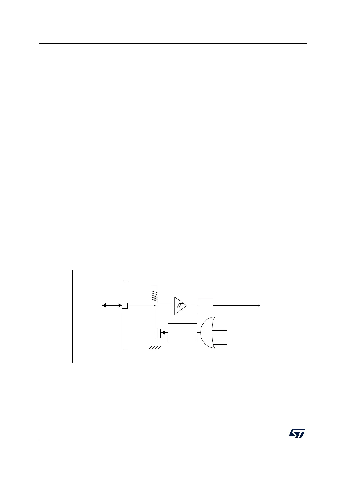
Figure 12. Simplified diagram of the reset circuit
NRST
R
PU
V
DD
/V
DDA
WWDG reset
IWDG reset
Pulse
generator
Power reset
External
reset
(min 20 μs)
System reset
Filter
Software reset
Low-power management reset
ai16095c