RM0402 Rev 6 485/1163
RM0402 General-purpose timers (TIM2 to TIM5)
544
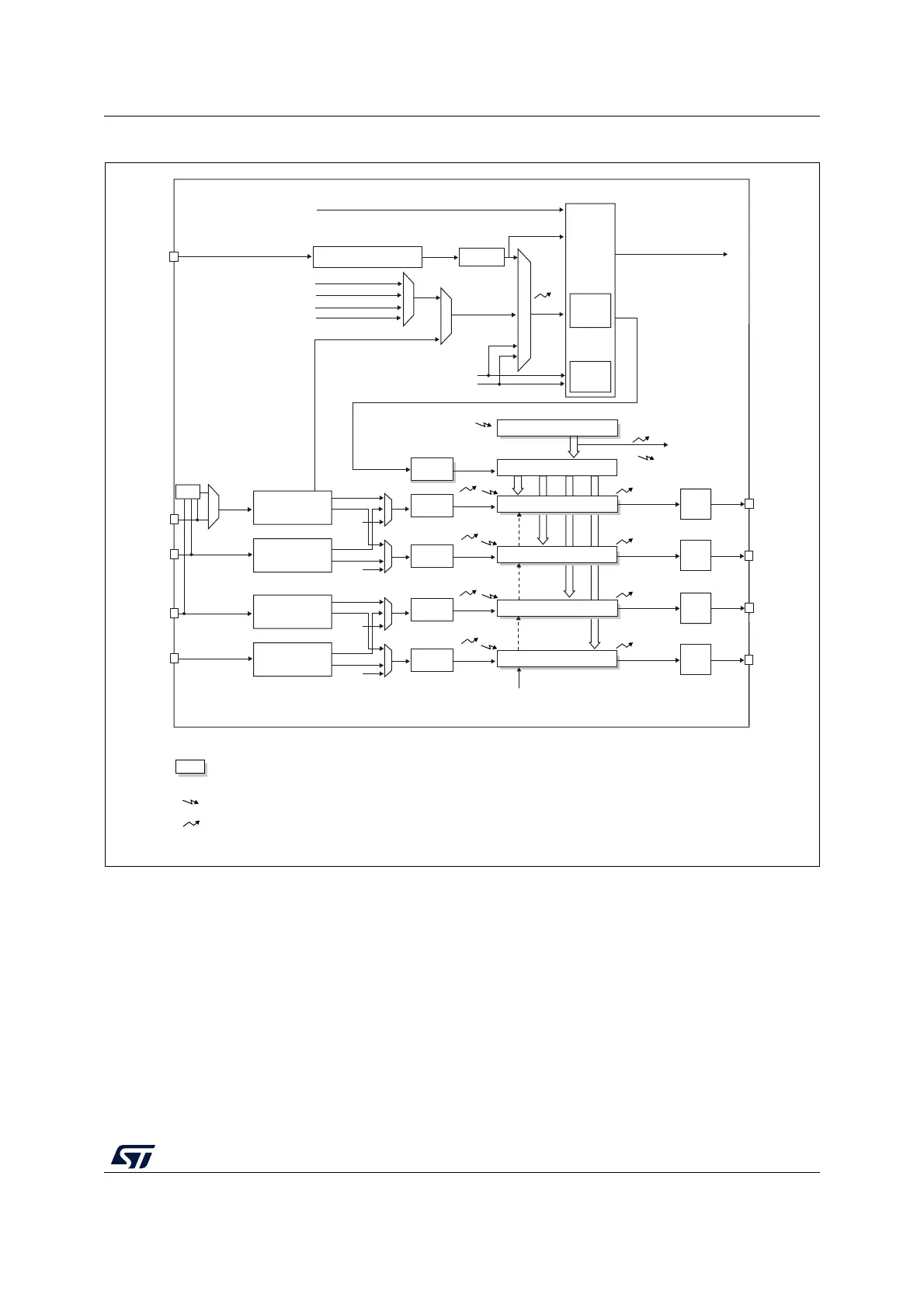
Figure 125. General-purpose timer block diagram
17.3 TIM2 to TIM5 functional description
17.3.1 Time-base unit
The main block of the programmable timer is a 16-bit/32-bit counter with its related auto-
reload register. The counter can count up. The counter clock can be divided by a prescaler.
The counter, the auto-reload register and the prescaler register can be written or read by
software. This is true even when the counter is running.
U
U
U
CC1I
CC2I
Trigger
controller
+/-
Stop, clear or up/down
TI1FP1
TI2FP2
ITR0
ITR1
ITR2
TRGI
Output
control
TRGO
OC1REF
OC2REF
U
UI
Reset, enable, up, count
CK_PSC
IC1
IC2
IC2PS
IC1PS
TI1FP1
TGI
TRC
TRC
ITR
TRC
TI1F_ED
CC1I
CC2I
TI1FP2
TI2FP1
TI2FP2
TI1
TI2
TIMx_CH1
TIMx_CH2
OC1
OC2
TIMx_CH2
TIMx_CH1
to other timers
to DAC/ADC
Slave
controller
mode
PSC
prescaler
CNT counter
Internal clock (CK_INT)
CK_CNT
TIMxCLK from RCC
ITR3
MS19673V1
XOR
Input filter &
edge detector
Capture/Compare 1 register
Notes:
Reg
Preload registers transferred
to active registers on U event
according to control bit
Event
Interrupt & DMA output
Auto-reload register
Capture/Compare 2 register
Prescaler
Prescaler
Input filter &
edge detector
Output
control
U
U
CC3I
CC4I
Output
control
OC3REF
OC4REF
IC3
IC4
IC4PS
IC3PS
TI4FP3
TI4FP4
TIMx_CH3
TIMx_CH4
OC3
OC4
TIMx_CH4
TIMx_CH3
Input filter &
edge detector
Capture/Compare 3 register
Capture/Compare 4 register
Prescaler
Prescaler
Input filter &
edge detector
Output
control
TRC
TI3FP3
TI3FP4
TRC
CC3I
CC4I
TI3
TI4
Encoder
interface
TIMx_ETR
Input filter
Polarity selection & edge
detector & prescaler
ETR
ETRP
ETRF
ETRF