Serial peripheral interface/ inter-IC sound (SPI/I2S) RM0402
820/1163 RM0402 Rev 6
– NSS output enable (SSM=0,SSOE = 1): this configuration is only used when the
MCU is set as master. The NSS pin is managed by the hardware. The NSS signal
is driven low as soon as the SPI is enabled in master mode (SPE=1), and is kept
low until the SPI is disabled (SPE =0).
– NSS output disable (SSM=0, SSOE = 0): if the microcontroller is acting as the
master on the bus, this configuration allows multimaster capability. If the NSS pin
is pulled low in this mode, the SPI enters master mode fault state and the device is
automatically reconfigured in slave mode. In slave mode, the NSS pin works as a
standard “chip select” input and the slave is selected while NSS line is at low level.
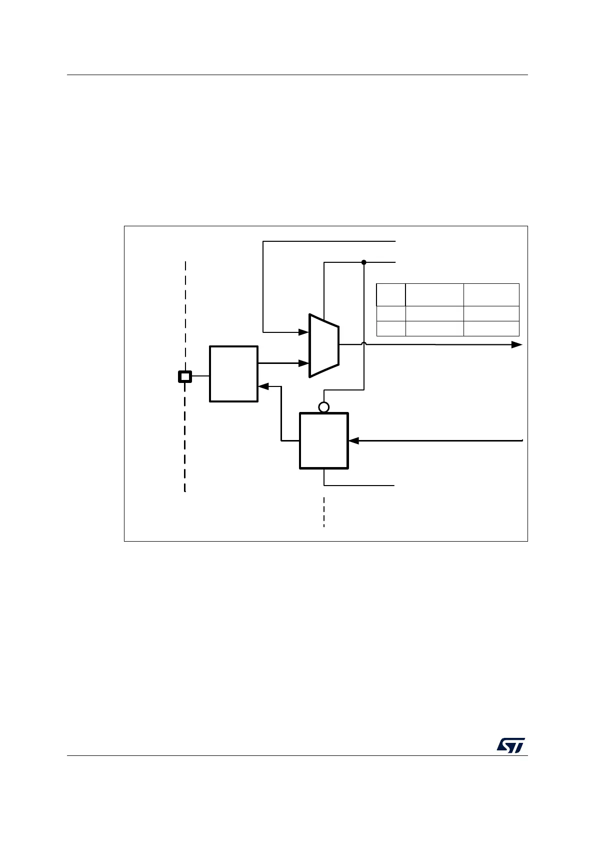
Figure 276. Hardware/software slave select management
1
0
NSS Input
SSM control bit
SSI control bit
SSOE control bit
NSS Output
NSS
pin
(used in Master mode & NSS
HW management only)
NSS
Output
Control
Master
mode
Slave mode
Non activeOKVdd
NSS
Inp.
ActiveConflictVss
NSS external logic
NSS internal logic
GPIO
logic
aiv14746e